GB-1
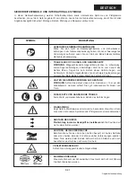
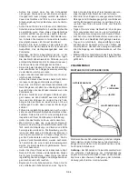
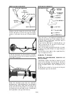
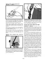
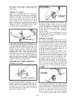
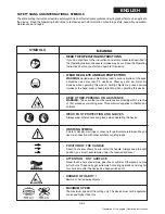
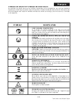
SAFETY SIGNS AND INTERNATIONAL SYMBOLS
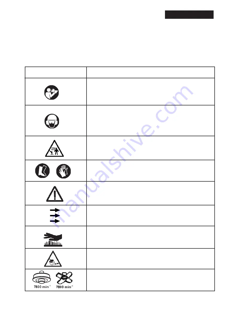
These Operating Instructions describe safety symbols and international symbols and pictographs that may be applied to
the device. Read the Operating Instructions to familiarise with all information concerning safety, assembly, operation,
maintenance and repair.
•
WARNING SYMBOL
Points to danger, warnings or reasons for particular carefulness. May be
used in connection with other symbols or pictographs.
•
READ THE OPERATING INSTRUCTIONS
If you do not adhere to the instructions and safety measures described in
the Operating Instructions severe injuries may occur. Read the Operating
Instructions before you start and operate this device.
• WEAR HEAD, EYE AND EAR PROTECTORS
WARNING:
Hurled-away objects may lead to serious injuries of the eyes,
excessive noise may result in deafness. Wear eye and ear protection
devices when operating this device. Falling objects may cause serious
injuries of the head; wear a head protection when operating this device.
•
DANGER OF INJURY !
Beware of hurled-away objects.
•
KEEP OTHER PERSONS ON A DISTANCE
WARNING:
Take care that no other persons are standing within a radius
of 15m around your working area. This particularly applies to children and
animals.
SYMBOLS
MEANING
•
WEAR FOOT PROTECTION AND GLOVES
Always wear safety boots and gloves when operating the device.
•
ATTENTION : HOT SURFACE
Never touch a hot exhaust pipe, gear box or cylinder. Otherwise, you may
suffer burns.These parts get extremely hot during operation and stay hot
for some time after the device has been switched off.
•
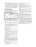
POSITION OF THE HANDLE
Direction of arrow shows how to install the handle. Always keep the right
position, you must never remain under the required distance !
•
MAXIMUM SPEED
The maximum speed of the cutting unit. The device must not be operated
at a speed higher than this.
ENGLISH
Translation of the original Operating Instructions
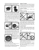
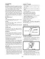
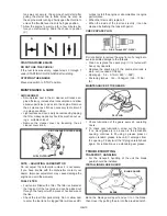
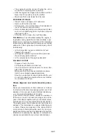
Summary of Contents for BT 4344
Page 2: ......
Page 94: ...GR 1 15 ELLHNIKA...
Page 96: ...15 15 GR 3...
Page 97: ...Raynaud GR 4...
Page 98: ...M5xl6 M5x20 M5x25 X 2 X 2 1 1 2 2 2x16 3 A B GR 5...
Page 99: ...A 3 B A S 4 mm 2x16 A B x x GR 6...
Page 100: ...15 16 15 METERS 50 FEET 15 GR 7...
Page 101: ...Monofil 2 5 mm KNIFE SIDE RAISED ANGLE TO GROUND ANGLE TO WALL 2 3 4 5 1 1 2 3 4 5 GR 8...
Page 102: ...1 2 1 5 cm 5 4 3 1 2 2 4 1 5 cm 2 5 mm 2 2 1 m 2 2 cm 15mm 3 255 mm GR 9...
Page 103: ...89 30 1 2 2 30 1 89 30 1 2 30 1 1 2 3 4 3 4 GR 10...
Page 104: ...5 6 1 2 3 4 5 STOPP l Stopp START 2 7 10 CHOKE 3 A 4 5 B 6 7 C A B C 3 7 Stopp STOP GR 11...
Page 105: ...O 6 0 7mm 0 023 O 028 0 6 0 7 mm 145 155 kg cm 1 25 2 GR 12...
Page 106: ...2 GR 13...
Page 107: ...1 0 6 0 7 mm Stop 2 3 0 6 0 7 mm 0 3 0 4 mm 4 GR 14...
Page 108: ......
Page 114: ......
Page 119: ......

