syndrome affecting the fingers of certain individu-
als may be brought about by exposure to vibration
and cold. Exposure to vibration and cold may cause
tingling and burning sensations followed by loss of
colour and numbness of the fingers. The following
precautions are strongly recommended as the mini-
mum exposure which might trigger the condition is
unknown.
• Keep your body warm, especially the head, neck,
feet, ankles, hands and wrists. Maintain good blood
circulation by performing vigorous arm exercises
during frequent work breaks and also by not smok-
ing.
• Limit the hours of operation. Try to fill each day with
jobs where operating the brush cutter or other hand-
held power equipment is not permanently required.
• If you experience discomfort, redness and swelling
of the fingers followed by whitening and loss of feel-
ing, consult your physician before further exposing
yourself to cold and vibration.
• Always wear ear protection, loud noise over a long-
er time may make cause hearing defects or even
deafness.
• Full face and head protection must be worn to pre-
vent injuries from falling objects or branches.
• Wear grip-safe heavy-duty work gloves to improve
your grip on the brush cutter handle. Gloves also re-
duce the transmission of vibrations to your hands.
• WARNING: The operating range of the cutter is still
dangerous while the device is coasting to a halt.
ASSEMBLY
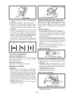
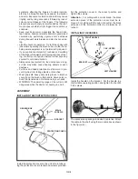
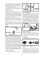
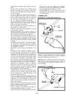
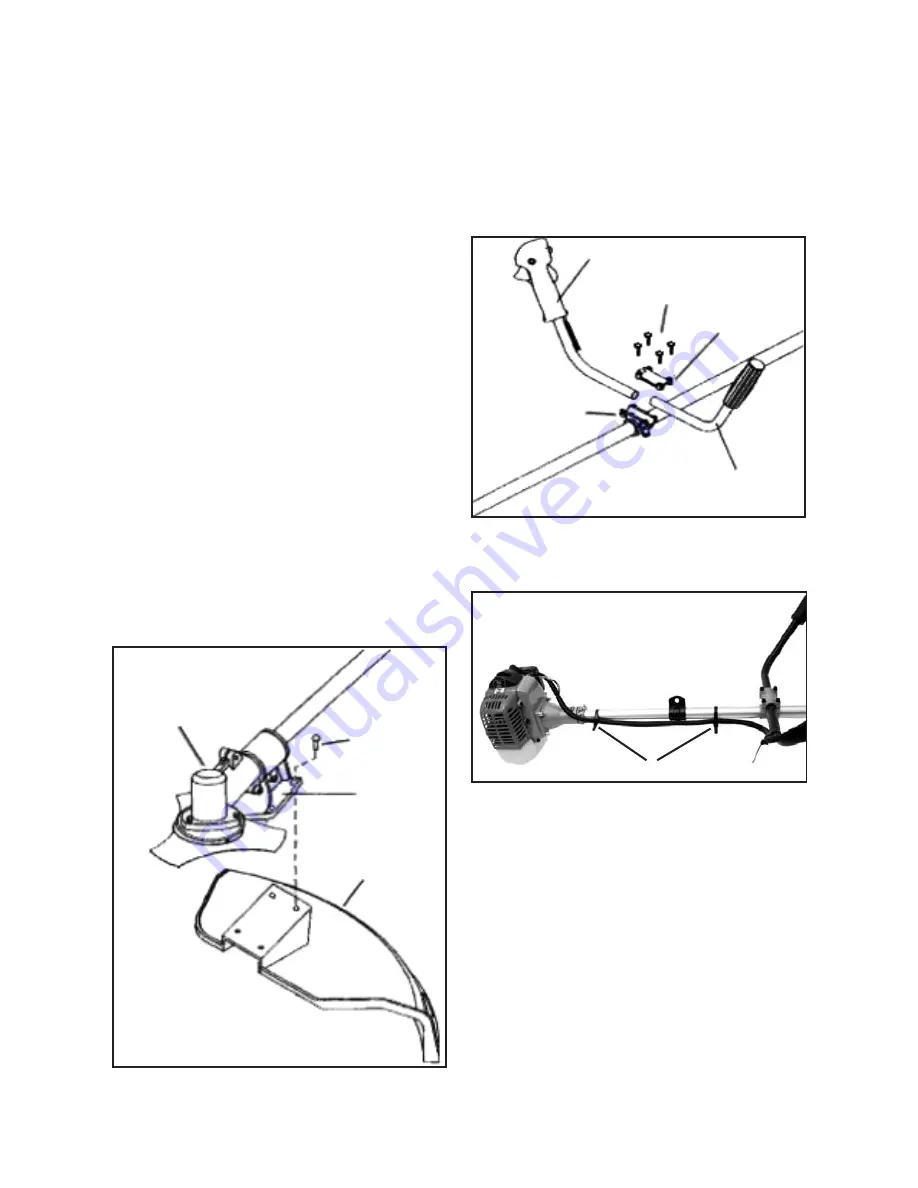
INSTALLING THE PROTECTION COVER
GEGEAR BOX
M5xl6
SCREWS
BRACKET
PROTECTION COVER
Install the protection cover on the unit’s main tube us-
ing the protection cover bracket and screws provided.
GB-4
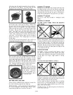
Put the protection cover in the correct position and
tighten the screws.
Attention :
For cutting with a metal blade, the black
extension piece of the protection cover must be re-
moved. For cutting with the nylon line cutter, the black
extension of the protection cutter must always be at-
tached.
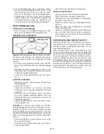
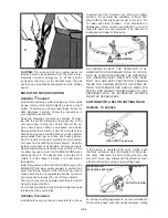
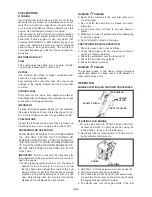
INSTALLING THE HANDLE
LEFT HANDLE
RIGHT HANDLE
M5x25
SCREWS
BRACKET
CAP, UPPER
Install the handle on the bracket. Put the handle in a
comfortable operating position and tighten the four M5
X 25 screws.
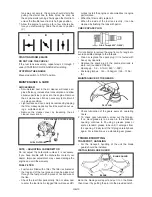
X
The accessories package includes 2 cable ties. Attach
the cable to the shaft using the two cable ties as shown
in the figure (X).
Summary of Contents for BT 4344
Page 2: ......
Page 94: ...GR 1 15 ELLHNIKA...
Page 96: ...15 15 GR 3...
Page 97: ...Raynaud GR 4...
Page 98: ...M5xl6 M5x20 M5x25 X 2 X 2 1 1 2 2 2x16 3 A B GR 5...
Page 99: ...A 3 B A S 4 mm 2x16 A B x x GR 6...
Page 100: ...15 16 15 METERS 50 FEET 15 GR 7...
Page 101: ...Monofil 2 5 mm KNIFE SIDE RAISED ANGLE TO GROUND ANGLE TO WALL 2 3 4 5 1 1 2 3 4 5 GR 8...
Page 102: ...1 2 1 5 cm 5 4 3 1 2 2 4 1 5 cm 2 5 mm 2 2 1 m 2 2 cm 15mm 3 255 mm GR 9...
Page 103: ...89 30 1 2 2 30 1 89 30 1 2 30 1 1 2 3 4 3 4 GR 10...
Page 104: ...5 6 1 2 3 4 5 STOPP l Stopp START 2 7 10 CHOKE 3 A 4 5 B 6 7 C A B C 3 7 Stopp STOP GR 11...
Page 105: ...O 6 0 7mm 0 023 O 028 0 6 0 7 mm 145 155 kg cm 1 25 2 GR 12...
Page 106: ...2 GR 13...
Page 107: ...1 0 6 0 7 mm Stop 2 3 0 6 0 7 mm 0 3 0 4 mm 4 GR 14...
Page 108: ......
Page 114: ......
Page 119: ......

