GB-10
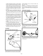
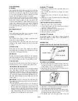
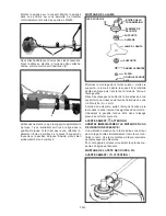
tank was not empty, the engine should start after
pulling the starter one to three times. As soon as
the engine starts running shortly open the throttle to
unlock the throttle lever from its half-gas position.
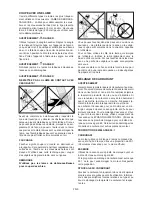
7. Allow the engine to warm up for a few minutes be-
fore you start working. Slide the choke to position
(C).
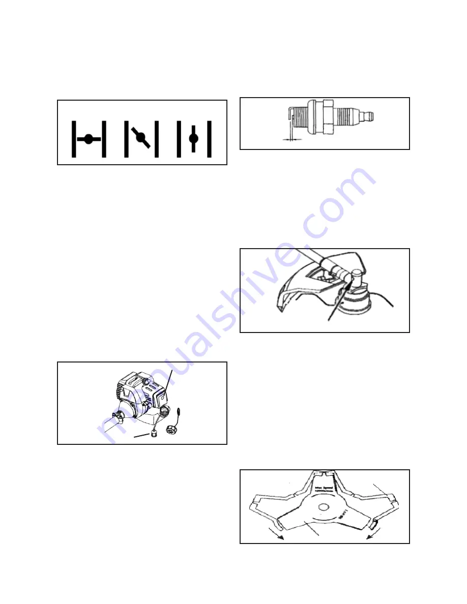
A
B
C
STARTING WARM ENGINE
DO NOT USE THE CHOKE !
If the fuel tank was empty, repeat steps 3 through 7
under STARTING COLD ENGINE after refilling.
STOPPING THE ENGINE
Move stop switch to ‘STOP’ position.
MAINTENANCE & CARE
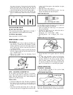
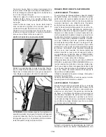
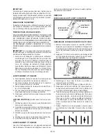
AIR CLEANER
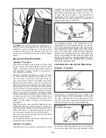
• Accumulated dust in the air cleaner will reduce en-
gine efficiency, increase fuel consumption and allow
abrasive particles to pass into the engine. Remove
the air cleaner as often as necessary to maintain it
in a clean condition.
• Light surface dust can easily be removed by tapping
the filter. Heavy deposits should be washed out us-
ing a suitable solvent.
• Remove the cleaner cover by loosening the air
cleaner cover knob.
AIR CLREANER COVER KNOB
FUEL FILTER
NOTE – ADJUSTING CARBURETTOR
Do not adjust the carburettor unless it is necessary.
If you have trouble with the carburettor contact your
dealer. Improper adjustment may cause damage the
engine and void the warranty.
FUEL FILTER
• Fuel tank is fitted with a filter. The filter is situated at
the free end of the fuel pipe and can be picked out
through the fuel port with a piece of hooked wire or
the like.
• Check the fuel filter periodically. Do not allow dust
to enter the fuel tank. A clogged filter will cause diffi-
culties to start the engine or abnormalities in engine
performance.
• When the filter is dirty replace it.
• When the inside of the fuel tank is dirty, it can be
cleaned by flushing the tank with petrol.
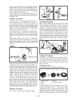
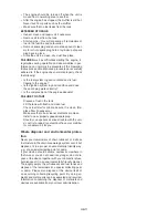
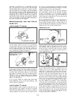
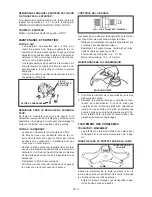
CHECK SPARK PLUG
O.6-0.7mm(0.023“-O.028“)
Do not attempt to remove the plug from a hot engine to
avoid possible damage to the threads.
• Clean or replace the spark plug if it is fouled with
heavy oily deposits.
• Replace the spark plug if the centre electrode is
worn-out (rounded at the tip).
• Spark gap : 0.6 – 0.7mm (.023“ – .028“)
• Fastening torque : 145 – 155kg/cm (125 – 135in/
lb)
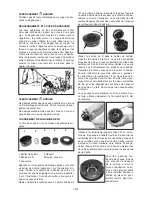
MAINTENANCE OF THE GEARS
FILL PLUG
1 Check lubrication of the gears every 25 operating
hours.
2 To check gear lubrication, screw out the fill plug.
If no more grease is to be seen in the lubrication
opening, continue to fill, using a grease press or
some standard grease tube until it emerges from
the opening. Finally twist the fill plug carefully back
again. For lubrication use a standard gear grease.
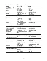
TROUBLESHOOTING
TRANSPORT, HANDLING
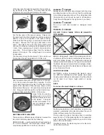
• For the transport, handling of the unit the blade
guard should be installed.
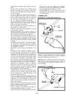
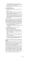
INSTALLING BLADE GUARD
BLADE
BLABE GUARD
Bend the blade guard apart and put it on the blade,
then close it by putting the pin into the provided notch.
Summary of Contents for BT 4344
Page 2: ......
Page 94: ...GR 1 15 ELLHNIKA...
Page 96: ...15 15 GR 3...
Page 97: ...Raynaud GR 4...
Page 98: ...M5xl6 M5x20 M5x25 X 2 X 2 1 1 2 2 2x16 3 A B GR 5...
Page 99: ...A 3 B A S 4 mm 2x16 A B x x GR 6...
Page 100: ...15 16 15 METERS 50 FEET 15 GR 7...
Page 101: ...Monofil 2 5 mm KNIFE SIDE RAISED ANGLE TO GROUND ANGLE TO WALL 2 3 4 5 1 1 2 3 4 5 GR 8...
Page 102: ...1 2 1 5 cm 5 4 3 1 2 2 4 1 5 cm 2 5 mm 2 2 1 m 2 2 cm 15mm 3 255 mm GR 9...
Page 103: ...89 30 1 2 2 30 1 89 30 1 2 30 1 1 2 3 4 3 4 GR 10...
Page 104: ...5 6 1 2 3 4 5 STOPP l Stopp START 2 7 10 CHOKE 3 A 4 5 B 6 7 C A B C 3 7 Stopp STOP GR 11...
Page 105: ...O 6 0 7mm 0 023 O 028 0 6 0 7 mm 145 155 kg cm 1 25 2 GR 12...
Page 106: ...2 GR 13...
Page 107: ...1 0 6 0 7 mm Stop 2 3 0 6 0 7 mm 0 3 0 4 mm 4 GR 14...
Page 108: ......
Page 114: ......
Page 119: ......

