GB
|
Operating Instruction
GB-2
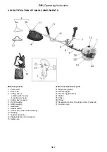
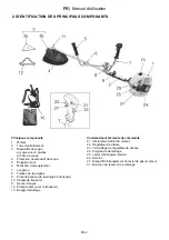
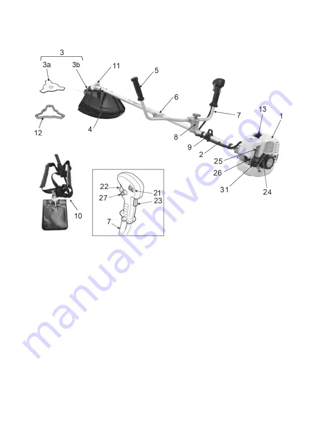
2. IDENTIFICATION OF MAIN COMPONENTS
Main Components
1. Power Unit
2. Drive tube
3. Cutting device
a. Blade with 3 points
b. Cutting line head
4. Cutting device guard
5. Front handgrip
6. Shaft coupling
7. Handlebar
8. Handle holder
9. Connection ponit (of the webbing)
10. Webbing
11. Angle transmission
12. Blade protection (for transport)
13. Spark plug
Controls and functional parts
21. Engine stop switch
22. Throttle trigger
23. Throttle trigger lockout
24. Starter
25. Choke
26. Primer
27. Accelerator shutter (1Locking button) (if present)
31. Fuel tank cap
Summary of Contents for IBF 43
Page 2: ...1...
Page 3: ...2...
Page 4: ...3...
Page 86: ...RU RU 2 2 1 2 3 a b 4 5 6 7 8 9 10 11 12 13 21 22 23 24 25 26 27 31...
Page 88: ...4 A 1 2 2 3 4 5 e 6 B 1 2 3 4 5 RU 4 RU...
Page 89: ...RU 6 7 C 1 2 3 4 3 15 30 5 6 7 8 9 10 11 D 1 2 3 4 5 6 7 8 9 E 1 RU 5...
Page 90: ...RU 2 F G 5 1 1 4 5 2 3 1 5 6 8 7 2 2 2 4 2 1 3 4 3 3 4 1 2 3 3 4 1 2 3 6 7 4 4 4 RU 6...
Page 93: ...RU 2 6 8 6 2 1 STOP 8 8 7 5 7 5 1 2 2 1 2 2 2 3 2 4 RU 9...
Page 94: ...RU 2 a 9 b 15 10 30 11 12 13 6 9 RU 10...
Page 95: ...RU 11 14 8 10 3 1 2 2 2 1 3 15 100 16 1 10 17 17 A B C 18 19 1 2 3 RU...
Page 96: ...RU 12 2 3 RU 6 8 8 8 8 5 10...
Page 97: ...RU 13 11 12 RU...
Page 100: ...UA UA 2 2 1 2 3 4 5 6 7 8 9 10 11 12 13 21 22 23 24 25 26 27 31...
Page 102: ...4 A 1 2 2 3 4 5 6 1 2 3 4 5 6 7 UA 4 UA...
Page 103: ...UA C 1 2 3 4 3 15 30 5 6 7 8 9 10 11 D 1 2 3 4 5 6 7 8 9 E 1 2 F UA 5...
Page 107: ...UA 8 8 7 5 7 5 1 2 2 1 2 2 2 3 2 4 2 a 9 UA 9...
Page 108: ...UA b 15 10 30 11 12 13 6 9 14 8 10 3 1 2 UA 10...
Page 109: ...UA 11 2 2 1 3 15 100 16 1 10 17 17 A B C 18 19 1 2 3 2 3 UA...
Page 110: ...10 6 8 8 8 8 5 UA 12 UA...
Page 111: ...UA 13 11 12 UA...
Page 134: ......


