background image

RECOMMENDATIONS

This equipment is designed for use in an industrial environment. However, we recommend you follow the 

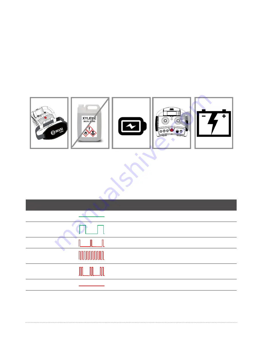
instructi ons below to extend the life span of your remote control set:

•  Use the belt provided with the transmitt er to prevent the transmitt er from falling.

•  Do not clean the transmitt er with solvents or pressurised water. Use a damp cloth or soft  brush.

•  Use and recharge the batt ery regularly.

•  Check the pushbutt ons. In case they show sings of deteriorati on, please contact the Authorized Technical 

Service.

•  Check if the batt ery contacts are correct. Otherwise, replace them.

04- MAINTENANCE

04- MAINTENANCE AND TROUBLESHOOTING

05- TROUBLESHOOTING

The transmitt er has status monitoring LED’s, which help to identi fy irregulariti es. The most common signals are 

contained in the tables below:

LED COLOUR / 

FREQUENCY (SOUND)

PULSE 

FREQUENCY

MEANING

ACTION

Green / 

Conti nuous (No sound)

The transmitt er works properly. OPERATION 

mode OK

OK

Green / 

Pulses (No sound)

STANDBY mode. If transmitt er is 4 minutes 

ON and no acti on has been taken.

Push START to return 

to the OPERATION 

mode

Red / 

Slow pulses (Beep)

Batt ery low signal. In 5 minutes you need to 

change bat.

Replace Batt ery with a 

Fully charged one.

Red/ 

Fast pulses (Beep)

EEPROM module missing or corrupt.

Check EEPROM module 

or reprogram if neces-

sary.

Red / 

Double pulses (Beep)

A manoeuvreis acti vated at transmitt er star-

tup process. HW Damage if no order is acti ve.

Release manoeuvreor 

replace transmitt er if 

necessary

Red / 

Conti nuous (Beep)

Transmitt er’s general failure. HW damage

ReplaceTransmitt er

Summary of Contents for IK 3

Page 1: ...IK 3 USER s MANUAL Paseo Miramón 170 20014 Donostia San Sebastián Guipúzcoa Spain tlc ikusi com ...

Page 2: ...ht one Identify the machine controlled on the label for this purpose on the transmitter or by using the display in case it has one j Service the equipment periodically k When carrying out repairs only use spare parts supplied by IKUSI dealers WARNING The devices muts be used with the manufacturers battery and battery charger The equipment must be operated by quialified personnel After use never lea...

Page 3: ...ts 4 Contact key 5 Start Pushbutton 6 STOP button 7 Option Range Limiter 8 External and extractable EP70 EEPROM module 9 Battery 10 3 5 TFT Display 11 Lateral pushbuttons 02 TECHNICAL DESCRIPTION 254 181 16 216 56 7 1 2 3 5 6 8 9 10 02 TECHNICAL DESCRIPTION ...

Page 4: ...hould now light indicating that the transmitter is transmitting Once the Tx is connected press on any of the transmitter s manoeuvre buttons and its correspon ding relay will be activated Check to make sure all the other manoeuvres work in a coherent way with the expected movements crane xx1 0 1 0 1 2 Turn the contact key to the position I It is not neces sary to take off the next times you want to...

Page 5: ...ter has status monitoring LED s which help to identify irregularities The most common signals are contained in the tables below LED COLOUR FREQUENCY SOUND PULSE FREQUENCY MEANING ACTION Green Continuous No sound The transmitter works properly OPERATION mode OK OK Green Pulses No sound STANDBY mode If transmitter is 4 minutes ON and no action has been taken Push START to return to the OPERATION mod...

Page 6: ...acts Do not carry charged batteries in toolboxes or next to other metal objects keys coins etc Always keep contacts clean Never leave batteries in direct sunlight The battery charger has two charging compartments that can simultaneously charge two batteries Connect the charger to the mains using the power source and cable supplied The red LED will switch The battery charger has two charging compar...

Page 7: ...MECHANICAL SPECS 06 CHARGER AND BATTERY ...

Reviews: