background image

Tx Cr 1

Cr 1

These instructi ons must be read carefully in order to install and use the set properly and to 

keep it in perfect working conditi on and to reduce the risks of misuse. 

Do not use this set on machines in potenti ally explosive atmospheres, except the models 

certi fi ed ATEX/RATEX to work in that conditi ons.

a) 

Strictly adhere to the instructi ons for installati on contained in this manual.

b) 

Make sure that professional and competent personnel carry out the installati on.

c) 

Ensure that all site and prevailing safety regulati ons are fully respected.

d) 

Make sure that this manual is permanently available to the operator and maintenance personnel.

e) 

Keep the transmitt er out of reach of unauthorised personnel.

g) 

On starti ng each working day, check to make sure that the STOP butt on and other safety measures  


are working.

h) 

When in doubt, press the STOP butt on.

i) 

Whenever several sets have been installed, make sure the transmitt er you are going to use is the  


right one. Identi fy the machine controlled on the label for this purpose on the transmitt er or by    


using the display (in case it has one).

j) 

Service the equipment periodically.

k) 

When carrying out repairs, only use spare parts supplied by IKUSI dealers.

WARNING

• 

The equipment must be operated by qualifi ed personnel.

• 

Aft er use, never leave the equipment ON (one or several transmitt ers). Always set the STOP butt on to 

switch  off   positi on  of  the  equipment  to  avoid  accidentally  to  acti vate  manoeuvres  –specially  in  crane 

maintenance purposes-.

• 

Do not use the set when visibility is limited.

• 

Avoid knocking or dropping the set.

• 

Do not use the set if failure is detected.

REMEMBER

Changes or modifi cati ons not expressly approved by IKUSI could void the user’s authority to operate this 
equipment.

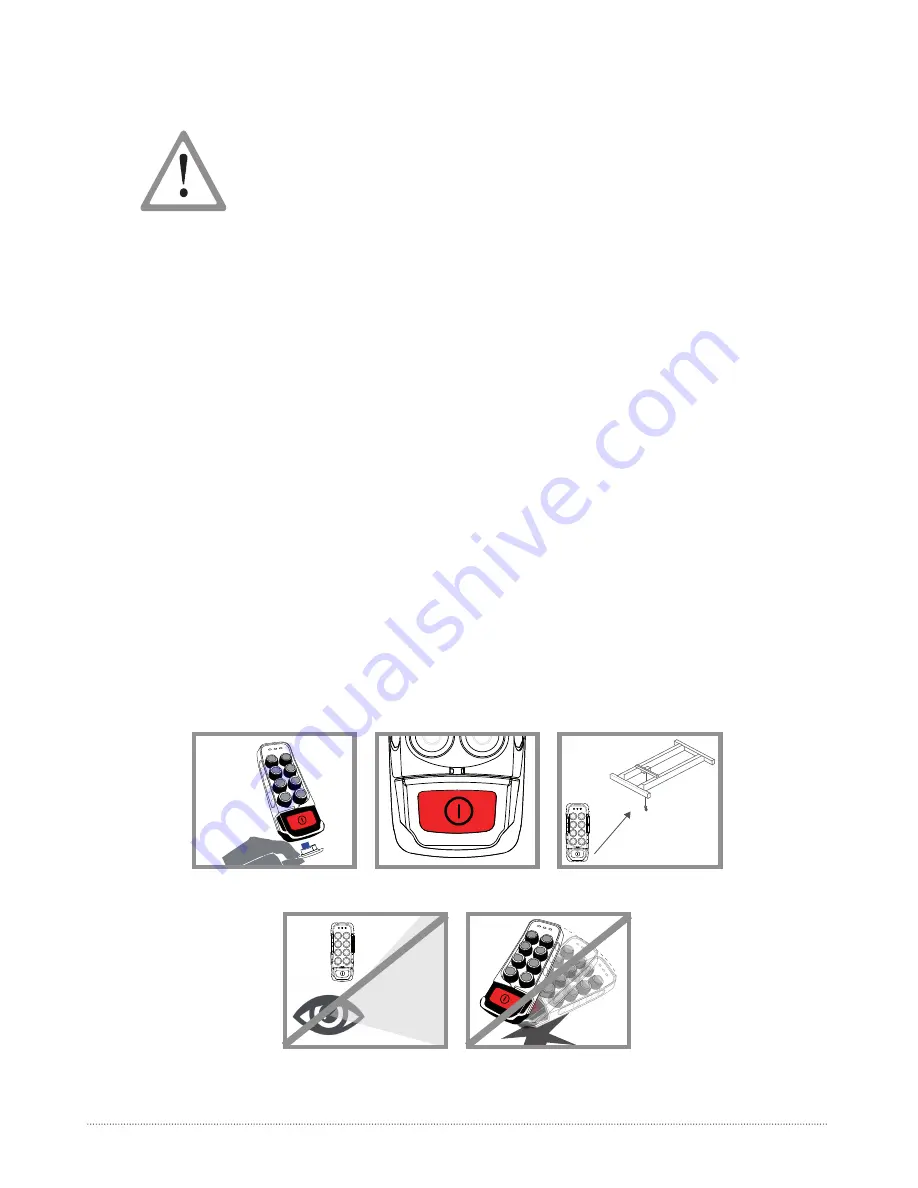
Remove the EEPROM in order to 

disable the transmitter

When in doubt, press the STOP 

button

Make sure the transmitter works 

with the machine to be handled

Do not use the set when visibility 

is limited

Avoid knocking or dropping the 

set

01- SAFETY INSTRUCTIONS

01- 

S

AFETY INSTRUCTIONS

Summary of Contents for IKORE

Page 1: ...ikore USER s MANUAL Paseo Miramón 170 20014 Donostia San Sebastián Guipúzcoa Spain tlc ikusi com ...

Page 2: ...ke sure the transmitter you are going to use is the right one Identify the machine controlled on the label for this purpose on the transmitter or by using the display in case it has one j Service the equipment periodically k When carrying out repairs only use spare parts supplied by IKUSI dealers WARNING The equipment must be operated by qualified personnel After use never leave the equipment ON on...

Page 3: ...e ISED radio frequency RF Exposure rules This transmitter must not be co located or operating in conjunction with any other antenna or transmitter Le présent appareil est conforme à l exposition aux radiations FCC ISED définies pour un environnement non contrôlé et répond aux directives d exposition de la fréquence de la FCC radiofréquence RF et RSS 102 de la fréquence radio RF ISED règles d exposi...

Page 4: ...CAN ICES 3 B NMB 3 B This Class B digital apparatus complies with Canadian ICES 003 Cet appareil numérique de classe B est conforme à la norme canadienne ICES 003 ...

Page 5: ...LED 3 Manoeuvre pushbutton 4 STOP button 5 External and extractable EPROM module 6 Alkaline batteries 7 START pushbutton 8 Hoist selection pushbutton 175 68 47 56 4 02 TECHNICAL DESCRIPTION 02 TECHNICAL DESCRIPTION 6 1 2 3 4 5 3 8 7 ...

Page 6: ...le EEPROM Externa Battery Model 4 Pilas AAA Weight with Battery Grams 315 g Harness Tira elástica Bandolera Display na Cable Connection na Range Limiter na Associated receivers R11 Temperature range 20ºC 70ºC Relative Humidity Máx 95 without condensation Storage temperatura range 24h 25ºC 75ºC 13F 167ºF Storage temperatura range long periods 25ºC 55ºC 13F 131 ºF 02 TECHNICAL DESCRIPTION ...

Page 7: ...ll blink in blue until reach the Stand by mode and will turn in fixed blue 3 Press the start button The status LED will blink in green until the transmitter is linked with the receiver 4 When the receiver confirms the link the status LED will turn fixed green The system will be fully operational in order to action any maneouvre When the systems controls two hoists there will be a pushbutton for the s...

Page 8: ...OOTING The transmitter has status monitoring LED s which help to identify irregularities The most common signals of the Status LED are contained in the tables below LED COLOUR FREQUENCY PULSE FREQUENCY MEANING ACTION Blue Fast pulses Starting the system stablishing communica tion with radio and EEPROM Wait Blue Continuous Stand by Set up system waiting user s action PressSTART to enter in Operatio...

Reviews: