background image

RECOMMENDATIONS

This equipment is designed for use in an industrial environment. However, we recommend you follow the 

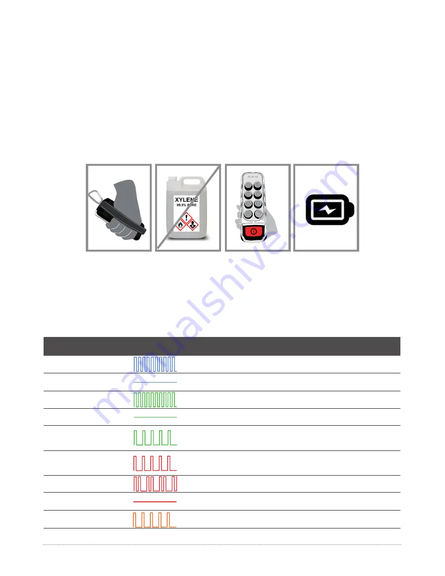
instructi ons below to extend the life span of your remote control set:

• 

Use the belt provided with the transmitt er to prevent the transmitt er from falling.

• 

Do not clean the transmitt er with solvents or pressurised water. Use a damp cloth or soft  brush.

• 

Check the pushbutt ons. In case of sings of deteriorati on, please contact the Authorized Technical Service.

• 

Check if the batt ery contacts are correct.

• 

Systems are supplied with a pack of AAA alkaline batt eries. AAA alkaline batt eries or rechargable batt eries 

can be used (the criti c batt ery period it is not guaranteed with these ones).

• 

It is recommended the use of new batt eries.

04- MAINTENANCE

04- MAINTENANCE AND TROUBLESHOOTING

05- TROUBLESHOOTING

The transmitt er has status monitoring LED’s, which help to identi fy irregulariti es. The most common signals of the 

Status LED

 are contained in the tables below:

LED COLOUR / 

FREQUENCY

PULSE 

FREQUENCY

MEANING

ACTION

Blue / 

Fast pulses

Starti ng the system, stablishing communica-

ti on with radio and EEPROM.

Wait

Blue/ 

Conti nuous

Stand-by.  Set up system, waiti ng user’s 

acti on.

PressSTART to enter in 

Operati on mode

Green / 

Fast pulses

Trying to link with the receiver and waiti ng its 

answer.

Wait

Green / 

Conti nuous

Working.

Operate

Green/ 

Slow pulses

Latency. If no acti on has been taken during a 

ti me.

Press START to return 

to Operati on mode

Red / 

Slow pulses

EEPROM Error. EEPROM module mising or 

corrupt.

Check EEPROM and 

reprogram if necessary 

Red / 

Double pulses

Radio Error. Radio communicati on error.

Replace transmitt er

Red / 

Conti nuous

Acti vated maneuvre or harware failure if no 

order is acti ve.

Release maneuvre or 

replace the transmitt er 

Orange / 

Slow pulses

Criti c batt ery signal.

Replace batt eries with 

charged ones.

Summary of Contents for IKORE

Page 1: ...ikore USER s MANUAL Paseo Miramón 170 20014 Donostia San Sebastián Guipúzcoa Spain tlc ikusi com ...

Page 2: ...ke sure the transmitter you are going to use is the right one Identify the machine controlled on the label for this purpose on the transmitter or by using the display in case it has one j Service the equipment periodically k When carrying out repairs only use spare parts supplied by IKUSI dealers WARNING The equipment must be operated by qualified personnel After use never leave the equipment ON on...

Page 3: ...e ISED radio frequency RF Exposure rules This transmitter must not be co located or operating in conjunction with any other antenna or transmitter Le présent appareil est conforme à l exposition aux radiations FCC ISED définies pour un environnement non contrôlé et répond aux directives d exposition de la fréquence de la FCC radiofréquence RF et RSS 102 de la fréquence radio RF ISED règles d exposi...

Page 4: ...CAN ICES 3 B NMB 3 B This Class B digital apparatus complies with Canadian ICES 003 Cet appareil numérique de classe B est conforme à la norme canadienne ICES 003 ...

Page 5: ...LED 3 Manoeuvre pushbutton 4 STOP button 5 External and extractable EPROM module 6 Alkaline batteries 7 START pushbutton 8 Hoist selection pushbutton 175 68 47 56 4 02 TECHNICAL DESCRIPTION 02 TECHNICAL DESCRIPTION 6 1 2 3 4 5 3 8 7 ...

Page 6: ...le EEPROM Externa Battery Model 4 Pilas AAA Weight with Battery Grams 315 g Harness Tira elástica Bandolera Display na Cable Connection na Range Limiter na Associated receivers R11 Temperature range 20ºC 70ºC Relative Humidity Máx 95 without condensation Storage temperatura range 24h 25ºC 75ºC 13F 167ºF Storage temperatura range long periods 25ºC 55ºC 13F 131 ºF 02 TECHNICAL DESCRIPTION ...

Page 7: ...ll blink in blue until reach the Stand by mode and will turn in fixed blue 3 Press the start button The status LED will blink in green until the transmitter is linked with the receiver 4 When the receiver confirms the link the status LED will turn fixed green The system will be fully operational in order to action any maneouvre When the systems controls two hoists there will be a pushbutton for the s...

Page 8: ...OOTING The transmitter has status monitoring LED s which help to identify irregularities The most common signals of the Status LED are contained in the tables below LED COLOUR FREQUENCY PULSE FREQUENCY MEANING ACTION Blue Fast pulses Starting the system stablishing communica tion with radio and EEPROM Wait Blue Continuous Stand by Set up system waiting user s action PressSTART to enter in Operatio...

Reviews: