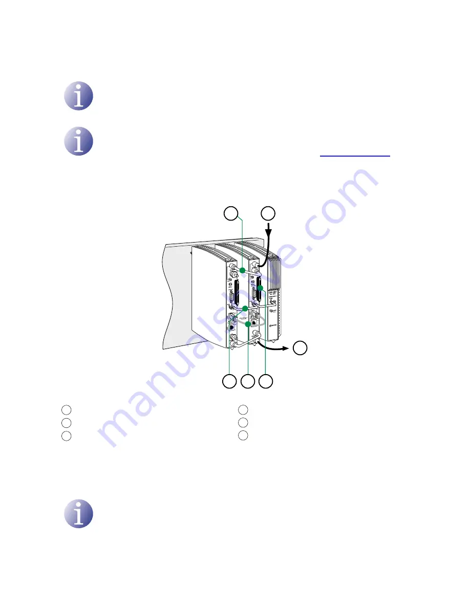
Basic installation and configuration/Assembly, connection of signals and power supply
8
Basic installation and configuration
NoTE
A PC with an Ethernet network card and a CAT-5E Ethernet crossover cable are
required for communication with the headend.
NoTE
To display the graphics provided in the headend configuration program correctly,
we recommend installing the Mozilla Firefox web browser (
www.mozilla.com
) in
the control PC.
Assembly, connection of signals and power supply
1)
Attach the modules to the base one by one following the instructions given in the
manuals for each module.
NoTE
IKUSI recommends the modules are assembled in the order shown in the above
figure:
J
Right: CFP-700/CFP-507 power supplies.
J
Left: STC-100 transmodulators
1
3
2
6
5
4
KEY
1
DVB-S/S2 signal input
2
DVB-T signal output
3
Bridging line in loop mode
4
Power supply bridges
5
IKUNET
6
CAM + Sma protection with safety
screws


