TM70Bi V3.2 (11/02)
1121174 L0.pdf
84
IKUSI reserves the right to change this information without prior notice.
22.- BINARY ROTARY SWITCH OPTION
22.1- MAIN CHARACTERISTICS
BINARY ROTARY SWITCH
Specifications
Supported transmsitter models
T70/1, T70/2 models with or without DLA option
Duty cycle
> 25.000 cycles
Vibration resistance
MIL-STD-202 / 201 A
Shock resistance
MIL-S-3785 (MIL-STD-202)
Humidity stress
90-95% / 40ºC during 240 hours (MIL-STD-202)
Number of positions per rotary switch
Maximun = 16 (4 bit) / BCD code binary output
Customized physical STOP limits
Adjustable from 0 to 15 pos. or without physical limits
Number of rotary switches per transmitter model
Maximum 2 (for T70/1 and T70/2 models)
Number of total positions
2
6
= 64 pos.(2 rotary switches, limited to pos. 10) Note(1)
Ingress degree
IP65
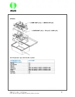
BININARY ROTARY SWITCH OPTION (REF. 2305236)
The binary rotary switch option wirh reference (2305236), contains the following Items
-
Binary rotary switch body (including physical STOP limits, without personalisation) Ref. 1102138
-
Selector handle (body, cover, arrow), Refs: 1107033 / 1107032 / 1107034
-
Silkscreen printing of the rotary switch in “gravoplay format” (numerichal marked from 0 to 15 pos.)
(NOT included in the KIT)
OPTIONAL UNDER DEMAND & PROJECT REQUIREMENTS
-
Cables of connection
22.2- A) OPERATING MODE WITH
T70/1 and T70/2 TRANSMITTER MODELS WITH DLA OPTION
.
The positions in which the binary rotary swtches can be assembled are the right ones that are not used for
programming mode (programming a spare part / changing the base cannel frequency)
(Prohibited positions: 1, 2 4,6, ON/OFF, START/KLAXON)
Note (1): To use more than 64 pos. with 2 rotary switches it is mandatory to use orders
from other pushbutton positions. These pushbuttons will be off.
Example: for 99 positions it is necessary to use orders from positions 7 and 8
pushbuttons, if the rotary switches are pleced in positions 9 and 10 in a T70/2
transmitter model.


