background image

INDEX

GUIDE TO THE MANUAL ......................................................................................................5

GENERAL INSTRUCTIONS  ..................................................................................................6

1

TRANSPORT ..............................................................................................................7

1.1

Packing ............................................................................................................................ 7

1.2

Transport ......................................................................................................................... 7

1.3

Unpacking ....................................................................................................................... 7

1.4

Machine handling  ............................................................................................................ 7

2

WORKING PARTS  .....................................................................................................8

3

MACHINE DESCRIPTION  ..........................................................................................9

3.1

Technical data  ................................................................................................................. 9

3.2

Electrical circuit  ............................................................................................................. 10

4

ACCESSORIES PROVIDED  ....................................................................................11

5

MACHINE INSTALLATION AND PREPARATION  ..................................................12

5.1

Checking for damage  .................................................................................................... 12

5.2

Environmental conditions .............................................................................................. 12

5.3

Positioning ..................................................................................................................... 12

5.4

Description of work station  ............................................................................................ 12

5.5

Graphics ........................................................................................................................ 13

5.6

Separate parts ............................................................................................................... 13

5.7

Connection to the mains ................................................................................................ 13

6

REGULATION AND USE OF THE MACHINE ..........................................................14

6.1

Setting ........................................................................................................................... 14

6.1.1

Adjusting the cutting depth  ............................................................................... 14

6.1.2

Setting the cutting spaces  ................................................................................ 15

6.1.3

Setting the cutting height  .................................................................................. 15

6.2

Cutting operations  ......................................................................................................... 16

6.3

Key cutting ..................................................................................................................... 16

6.4

BIT and DOUBLE BIT keys (side 1)  .............................................................................. 18

6.5

Pump keys (side1) ......................................................................................................... 19

7

MAINTENANCE ........................................................................................................20

7.1

Cutting tool replacement  ............................................................................................... 20

7.2

Tracer point replacement  .............................................................................................. 20

7.3

Replacing the fuses ....................................................................................................... 21

8

DISPOSING OF MACHINE .......................................................................................22

9

AFTER-SALES SERVICE  ........................................................................................23

9.1

How to request service .................................................................................................. 23

Summary of Contents for HALLEY BKA 2000

Page 1: ... DM318010 vers 3 0 Operating manual HALLEY BKA 2000 ...

Page 2: ...rights reserved No part of this publication may be reproduced or used in any form or by any means photocopying micro film or other without the written permission of ILCO ORION Edition june 2006 Printed in Vittorio Veneto by ILCO ORION via Podgora 20 Z I 31029 VITTORIO VENETO TV Italy ...

Page 3: ...g 12 5 4 Description of work station 12 5 5 Graphics 13 5 6 Separate parts 13 5 7 Connection to the mains 13 6 REGULATION AND USE OF THE MACHINE 14 6 1 Setting 14 6 1 1 Adjusting the cutting depth 14 6 1 2 Setting the cutting spaces 15 6 1 3 Setting the cutting height 15 6 2 Cutting operations 16 6 3 Key cutting 16 6 4 BIT and DOUBLE BIT keys side 1 18 6 5 Pump keys side1 19 7 MAINTENANCE 20 7 1 C...

Page 4: ......

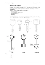
Page 5: ...ultation The contents of the manual are divided into sections relating to Transport and handling Description of machine and safety devices Proper use of the machine Maintenance Technical terms Common technical terms are used in this manual To assist those with little experience of key cutting below is an illustration of the terms used for the different parts of keys Fig 1 1 Head 2 Rim 3 Tip 4 Cuts...

Page 6: ...n order to make the best use of the HALLEY BKA 2000 key cutting machine and benefit from its potential Further risks There are no further risks arising from the use of the HALLEY BKA 2000 key cutting machine Protection and safety precautions for the operator The HALLEY BKA 2000 key cutting machine is built entirely to standards The operations for which it has been designed are easily carried out a...

Page 7: ...r things 1 3 Unpacking To remove the machine from the packing box 1 cut the straps with scissors and remove 2 open the box without damaging it as it may be used again e g removals dispatch to the manufacturers for repairs or servicing 3 check the contents of the box which should comprise 1 HALLEY BKA 2000 key cutting machine 1 safety device standard with 230V key cutting machines set of documents ...

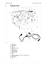
Page 8: ...iage lever D Base E Cutter nut F Lateral movement lever G Motor H Cutter protection I Key fastening knob L Clamp tracer side M Clamp cutter side N Tracer O Cutter X Safety device standard with 230V key cutting machines X1 Safety main switch X2 Warning light X3 Plug N L O F C D M A G B E H I I X1 X X2 X3 ...

Page 9: ...te that the machine is live Motor The HALLEY BKA 2000 has a direct drive motor G The transmission unit comprises the motor and cutter is protected by a single cover H Mobile unit The mobile unit comprises a carriage B holding the clamps The carriage B is fitted to the translation shaft and is moved manually by the operator It has been designed to avoid the accumulation of cutting dust or chippings...

Page 10: ...ion 4 3A The main parts of the electric circuit on the HALLEY BKA 2000 are listed below 1 Safety device inlet 2 Safety main switch 3 Warning light 4 Wiring clip 5 Machine inlet 6 Rapid fuses 4A 230V 10A 110V 7 Illuminated switch 8 Motor 230V a c 50Hz 110V a c 60Hz 9 Condenser 8 230V 20 110V Safety device standard with 230V key cutting machines F F 110V 230V 3 brown blue yellow green brown blue OUT...

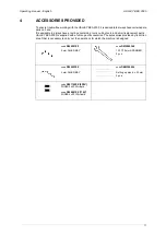
Page 11: ...tools and small replacement parts HALLEY BKA 2000 is supplied with a full range of accessories The accessories provided by Ilco Orion are all that is necessary to carry out the operations for which the machine is designed code D300221ZZ 2 mm ALLEN KEY code DMS200340 13 17 19 mm SPANNER 2 pcs code D300223ZZ 3 mm ALLEN KEY code DEM306054 Setting up pins 6 x 50 mm 2 pcs code D301185ZZ 230V FUSES 5x20...

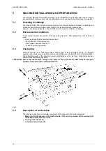
Page 12: ...sites should be avoided the conditions for the machine are temperature between 0 and 40 C relative humidity approx60 5 3 Positioning Place the machine on a horizontal surface solid enough to take the weight 26 Kg To facilitate operation and maintenance install the machine with a clearance of at least 300 mm on all sides fig 6 Check that the weight of the machine is evenly distributed over the four...

Page 13: ...t the free end of the power cable to the power mains Fig 7 110V version connect the key cutting machine and the power cable then connect the free end of the power cable to the power mains Fig 7 Fig 7 5 7 Connection to the mains It is extremely important for the operator s safety to ensure that the key cutting machine is connected to the power mains with the right voltage and by means of a properly...

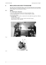
Page 14: ...hine efficiency 6 1 Setting 6 1 1 Adjusting the cutting depth 1 Insert the supplied gauges horizontally in the clamp housings side 1 fig 8 2 move the carriage and make sure the tracer is well pressed against the gauge 3 turn the cutter manually 4 the cutting depth of the machine is correct when the cutter skims the gauge freely Otherwise proceed as follows loosen the screw J1 fig 9 turn the screw ...

Page 15: ...ht clamp M Otherwise proceed as follows loosen the screw N1 of the tracer unit fig 11 move the tracer unit next to the gauge in the left clamp L fasten the screw N1 make sure the above mentioned condition occurs before the adjustment of the machine can be considered correct Fig 10 Fig 11 6 1 3 Setting the cutting height As for depth gauging The cutter must skim the gauge evenly independently of th...

Page 16: ...clamp to the desired side proceed as follows a loosen the clamp fastening knob I by turning it anticlockwise until the pins protrude from the guide b turn the clamps L and M and position them as desired c tighten the clamp fastening knob I until the clamps are fastened 6 3 Key cutting 1 Position the sample key into the left clamp L and fasten it position the key blank into the right M and fasten i...

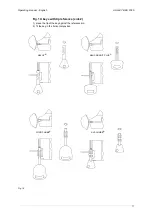
Page 17: ...nual English HALLEY BKA 2000 17 Fig 14 keys with tip reference side 2 1 place the tip of the key against the reference pin 2 fit the key in the horizontal position Fig 14 ABLOY FORD CHUBB AVA CHUBB ABUS GRANIT PLUS ...

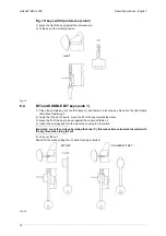
Page 18: ...nk into the right clamp M without fastening it 2 using the F and C levers move the bit of the key towards the tracer 3 place the bit of the key to be cut against the cutter and fasten it 4 loosen the carriage and turn the machine on using the A switch Important move the carriage by raising the knob C this makes it move towards the cutter with the key tilted thus aiding the cut 5 carry out the cut ...

Page 19: ...to the V shaped housing of the left clamp L make sure it presses against the side of the clamp and fasten it 3 in the same way fasten the key blank in the right clamp M 4 carry out the cut Important for flat pump keys proceed as follows 5 place the key in the clamp without fastening it 6 fasten the key using the screw X situated at the top of the clamp Fig 17 PUMP KEY X ...

Page 20: ...the manual to the letter use original spare parts always check that any screws or nuts removed when replacing a piece are properly tightened 7 1 Cutting tool replacement Using the supplied tools proceed as follows ATTENTION remove the mains plug 1 Place the 13 mm spanner onto the cutter shaft 2 place the 13 mm spanner onto the cutter fastening E nut 3 loosen the E nut by turning it clockwise fig 1...

Page 21: ...hine so that the fuse box is easily reached 2 remove the fuses box placed below the key cutting machine socket fig 20 3 replace the fuses U 4 close the fuses box and connect the power cable ATTENTION fuses must always be replaced with others of the same type rapid and with the same Amps 4 Amps on 230V 10 Amps on 110V Fig 20 U ...

Page 22: ...ontaminated or toxic noxious waste are listed in the appendices to the current European Union regulations regarding disposal of such waste INFORMATION FOR USERS as per art 10 of Directive 2002 96 CE of 27 01 2003 regarding waste from electric and electronic appliances RAEE The symbol illustrated above also found on the machine indicates that it has been placed on the market and must be included in...

Page 23: ... the manufacturer or recommended Ilco Orion Service Centres On the back cover of this manual is a list of the manufacturer s addresses listed below are the addresses of specialized service centres 9 1 How to request service The guarantee attached to the HALLEY BKA 2000 ensures free repairs or replacements of faulty parts within 12 months of the date of purchase All other service calls must be arra...

Page 24: ......

Page 25: ...ORIO VENETO TV ITALY TEL 0438 9136 FAX 0438 913800 Declares under its own responsibility that the Key cutting machine model HALLEY complies with the requirements of the following European Directives European Union DIRECTIVE 98 37 CEE Machines and with the EN 292 1 EN 292 2 Standards European Union DIRECTIVE 89 336 CEE Electromagnetic Compatibility and with the EN 55014 1 EN 61000 3 2 EN 61000 3 3 ...

Page 26: ...ILCO ORION via Podgora 20 Z I 31029 VITTORIO VENETO TV 0438 913636 Telefax 0438 913650 Internet www ilco orion it E mail ilco orion ilco orion it ...

Reviews: