background image

Ref.

Part no.

Description

1

045HD-1

Carriage

1X

045HD-1X

Carriage assembly

2

025-2

Carriage stud

3X

045HD-3X

Vise jaw assembly (Super Jaw 3)

4

025-4

Vise jaw spring

6X

025-6X

Thrust bearing set

8

025-8

Wing nut

9X

040-9X

Carriage handle

20

040HD-20

Cutter shaft bearings

21

025-21

Carriage shaft bushing

23

045HD-23

Carriage shaft

32

024B-32

Button head. screw, 10-24 x 

3

8

"

36

025-36

Cutter nut, N-4

37

025-37

Cutter spacer; left

38

P-X23MC

P-X23MC cutter

40

040HD-40

Cutter shaft

41

025-41

Cutter shaft pulley 

43

814-00-51

Nylon brush

45

024-45

Brush bolt washer, 

5

16

46A

025-46A

Hex head screw, 

5

16

-18 x 

3

4

47

025-47

Motor pulley 2" - 3L

48

025-48

V-Belt, 3L-180

49

045-49

Cutter guide (stylus)

50

040-50

Carriage stop

52

040-52

Socket hd. screw 8-32 x 1-1/2"

53

045-53A

Cutter guide binding washer

54

045-54

Cutter guide binding screw

55A

045-55A

Adjusting screw

56

040-56

Key gauge

57

024B-57

Key gauge bracket

58

024B-58

Key gauge dowel pin

59

025-59

Key gauge housing

60

025-60

Cap screw, 8-32 x 

1

2

"

61

025-61

Circuit Breaker, ETA 1658

62A

025-62A

On/Off switch

65

045HD-65

Machined base

68

040-68

Electrical cover

70

040-70

Rubber mount

74

040-74

Truss head screw, 8-32

75

040-75

Motor,

1

4

hp,115V

Ref.

Part no.

Description

79

024B-79

Key gauge spring

84

024B-84

Clip

86X

045HD-86X Safety hood assembly

87

045HD-87

Safety shield

89

045-89

#10 Lockwasher

90

025-90

Nut, #10-32

91

024B-91

Power cord

92

024B-92

3 wire motor cable

100

040HD-100

Cutter spacer; right

101

025-101

Motor pulley set screw

106

040-106

Chip tray

109

025-109

Bearing washer

110

025-110

Wave washer

129

040-129

Locking nut (8-32)

146

040-146

Power cord strain relief

150

040-150

Switch screw (6-32 x 1/4")

151

040-151

Set screw (8-32 x 3/8")

160

025-160

Caution label

163

045-163

Hood Screw

171

025-171

Cutter pulley set screw, 

3

8

" -18

181

024B-181

Key Gauge Spacer - Left

182

024B-182

Key Gauge Spacer - Right

183

040-183

1/4-20 Lockwasher

184

040-184

1/4-20 Hex Nut

186

045-186

6-32 x 3/8" set screw

187

045-187

dowel

188

045-188

dowel spring

189

045-189

Adjustment dial

190

045-190

Cutter guide label

194

045-194

#10 flat washer

195

045-195

10-32 x 1/2" Button hd. screw

198

045-198

7/16-14 x 3/4" set screw

199

045-199

1/2-20 x 1/2" set screw

IM

045HD-IM

Instruction manual

NS

025-240

220V 

1

4

HP motor

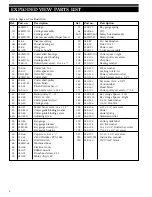
EXPLODED VIEW PARTS LIST

8

Refer to pages 6-7 for illustration

Summary of Contents for 045 HD

Page 1: ...045 HD INSTRUCTION MANUAL IMPORTANT Read these instructions before you use your new 045 HD Key Machine Ensure that all safety recommendations are followed See page 3 for instructions ...

Page 2: ...any the machine When seeking service information about this machine refer to Model No 045 HD and the part number desired see pages 6 to 8 Note that many parts are not inter changeable with other ILCO machines 2 CONTENTS Warranty 2 Safety information 3 Introduction unpacking 4 Operating parts illustrated 5 Operating parts identification names and part numbers 5 Exploded view 6 Exploded view parts l...

Page 3: ... should the mechanically driven parts of the machine be touched while it is in operation The operator should take care to ensure that loose fitting clothing long hair etc are kept from the area of machine operation Your machine has been specially designed and built for key cutting purposes only and should be operated according to the Operator s Manual All other uses are strongly discouraged as pot...

Page 4: ...lly suit ed to gripping these keys and is capable of gripping them in the groove or milling for enhanced clamping perfor mance when necessary Accurate easy to operate and maintain the model 045 HD delivers excellent performance at an economical Unpacking instructions The 045 HD has been engineered to duplicate cylinder paracentric keys It is not intended or designed for any other purpose The machi...

Page 5: ...ush 045 49 Cutter guide stylus 045 55A Adjusting screw 040 56 Key gauge 025 62A On Off switch 045 86X Safety hood assembly 045 87 Safety shield OPERATING PARTS 5 Key gauge Safety shield Nylon brush On Off power switch Carriage Vise jaw assembly Operating parts identification Wing nut Safety hood assembly Carriage shaft Cutter guide Depth Dial ...

Page 6: ...EXPLODED VIEW 6 ...

Page 7: ...EXPLODED VIEW 7 ...

Page 8: ...65 045HD 65 Machined base 68 040 68 Electrical cover 70 040 70 Rubber mount 74 040 74 Truss head screw 8 32 75 040 75 Motor 1 4hp 115V Ref Part no Description 79 024B 79 Key gauge spring 84 024B 84 Clip 86X 045HD 86X Safety hood assembly 87 045HD 87 Safety shield 89 045 89 10 Lockwasher 90 025 90 Nut 10 32 91 024B 91 Power cord 92 024B 92 3 wire motor cable 100 040HD 100 Cutter spacer right 101 02...

Page 9: ...ot grind away the shoulder 5 Don t run the cutter into the vise jaw this will dull the cutter and reduce cutter efficiency 6 Keep the cutter clean Don t let any foreign objects or instruments blunt it This cutter is a precise cutting tool and should be handled with care 7 Lubrication requirements for your new HD Performance Series key machine are minimized through the use of sealed permanently lub...

Page 10: ...nto contact with the carriage Both left and right vise jaws should be rotat ed to the same position Figure 2 Figure 1 General key duplication procedures WARNING Do not install or remove keys unless the off on switch is in the OFF position Always wear eye protection when operating this machine There are four procedures that the machine operator per forms to insure proper duplication of a key 1 Sele...

Page 11: ...ank must be properly aligned and securely clamped in the vise jaws To do this slide the machine s carriage assembly towards the right and position the appropriate key blank in the carriage s RIGHT vise jaw with the head of the blank pointing to the left Ensure that the shoulder of the key blank is located approximately 1 8 to the left of the vise jaw s left edge Holding the key blank firmly and le...

Page 12: ...regular jerking motion in the movement of the carriage Acquire a smooth steady motion using both hands on the carriage to guide it Apply the same degree of pressure each time a key is duplicated Excessive pressure may cause over cutting It is sometimes best to practice on a few keys until the operator learns to impart a steady uniform pressure to the carriage Figure 5 Replacing the Cutter The P 23...

Page 13: ...rely grazes the key blank before it while the cut ter guide is in contact with the other key blank Retighten the binding screw once the calibration process is com pleted Recheck after tightening to assure that adjust ment did not shift Each calibration mark on the depth adjustment dial is equivalent to approx 0015 1 1 2 thousandths of an inch As you can see this system can allow for very pre cise ...

Page 14: ...bolt and is adjustable To check the adjustment raise carriage without keys in vise jaws and rotate the cutter by hand The cutter should not contact the vise jaw When the carriage stop is properly adjusted there should be a space of 008 between the vise jaw and the cutter this is about the thickness of an ordinary busi ness card Do not allow a greater distance since this many affect the depth of cu...

Page 15: ...15 ...

Page 16: ...16 Printed in USA 125191 Kaba Ilco Corp P O Box 2627 27802 400 Jeffreys Rd Rocky Mount NC 27804 Tel 252 446 3321 Fax 252 446 4702 www kaba ilco com ...

Reviews: