background image

PROCESSOR

Mains isolator

I/O

Processor on/off switch

LABELS

IL793

I

0

ILF

OLAB FP40

ILFORD

ILFO

LAB FP40

50/60Hz

1st proof 14.12.95

OPERATING INFORMATION

ILFORD

ILFOLAB

FP40

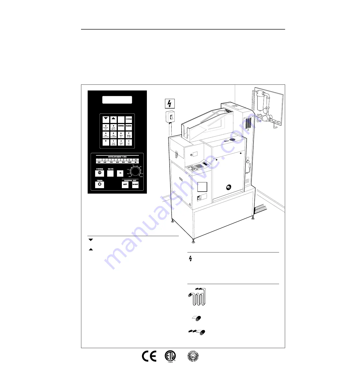
The following symbols are used 
to explain or highlight items or
actions that occur during use of
the ILFOLAB FP40 processor.

CONTROL PANEL

Forward through sequence

Back through sequence

ENTER

Record the new input data

CONFIRM

Verify the input data to memory

CLEAR

Clears the display, shows the
present state of the processor.
Press CLEAR at the start and end of 
each programming sequence

POWER

Switches the processor systems on

DRIVE

Switches on drive motor, air pump
and dryer

TIMER

Select for automatic switch on

I/O

Film in processor

Orientation of cassette

Film in loading box

Summary of Contents for ILFOLAB FP40

Page 1: ...une 1998 ILFORD Imaging UK Limited Mobberley Cheshire AIR PUMP ADJUSTMENTS The air pump controls air flow through the water in tank WS1 Remove rack 3 to see the amount of agitation With DRIVE on rotate the air pump adjusting knob clockwise to decrease the flow of air counter clockwise to increase the flow EMERGENCY PROCEDURES If the drive stops with a film in the processor fit the handle and turn ...

Page 2: ...ILFOLAB FP40 processor CONTROL PANEL Forward through sequence Back through sequence ENTER Record the new input data CONFIRM Verify the input data to memory CLEAR Clears the display shows the present state of the processor Press CLEAR at the start and end of each programming sequence POWER Switches the processor systems on DRIVE Switches on drive motor air pump and dryer TIMER Select for automatic ...

Page 3: ...M will power the pump through one complete cycle Power the pump through 5 cycles Take an average reading of the total volume to find the actual rate adjust the rate if required and check again Replenishment pump flow rates and operating times Rep volume Approximate rep time seconds ml 36 exp Fixer Developer and rinse solution 10 2 4 3 3 20 4 8 6 6 30 7 2 9 9 40 9 6 13 2 50 12 0 16 5 60 14 4 20 8 7...

Page 4: ... 6 TIMER SET and follow the instructions To set the days you want the timer to operate press 0 for off 1 for on DRAINING Remove lower panel withdraw bottle Remove top cap assembly Remove drain cap and fit nozzle pour out the effluent Refit caps replace bottle and refit panel Each working tank can be drained by opening the appropriate drain valve Place a bottle under the drain pipe Dev or Fix when ...

Reviews: