5-3
P71D0EA
C-SRP
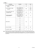
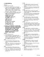
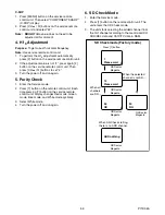
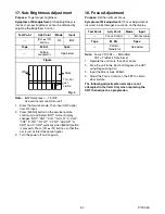
1. Press [MENU] button on the service remote
control unit. Then select “COMPONENT SHARP”
(C-SRP) display.
2. Press [CH
o
/
p
] buttons on the service remote
control unit and select “42.”
Note:
BRIGHT
data value does not need to be
adjusted at this moment.
4. H f
0
Adjustment
Purpose:
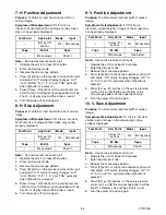
To get correct horizontal frequency.
Note:
Use service remote control unit.
1. To perform the H f
0
adjustment automatically,
press [2] button on the service remote control unit.
2. If the adjustment value is not “4”, press again [2]
button on the service remote control unit. Then
press [CH
o
/
p
] buttons to set “4.”
3. Turn the power off and on again.
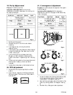
5. Purity Check
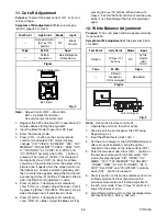
1. Enter the Service mode.
2. Press [7] button on the remote control unit. Each
time pressing [7] button on the service remote
control unit, display changes Red mode, Green
mode, Blue mode, and White mode cyclically.
3. Select White mode.
4. Turn the power off and on again.
6. SD Check Mode
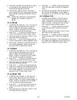
1. Enter the Service mode.
2. Press [1] button on the remote control unit. The
unit enters the SD-Check mode.
3. The unit starts selecting the added channel from
the first channel according to the memorized CH
ADD/DEL data and CATV/TV data in RAM.
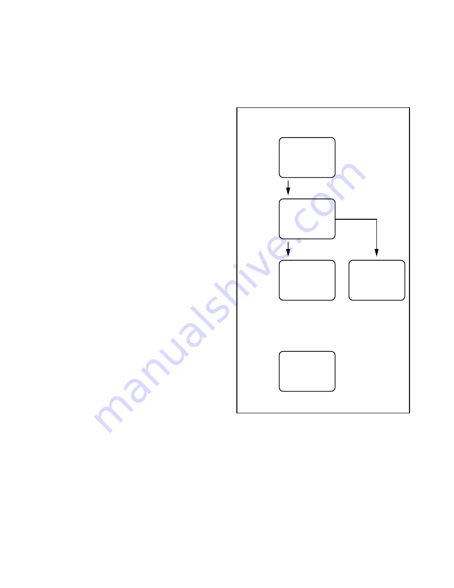
SD Check mode (Factory mode)
7
Please wait
OSD color:
Magenta
Press [1] button.
13
Please wait
OSD color:
Magenta
When the selected
channel is not SD,,,,
When all
channels
are SD,,,,
When SD-Check starting,
there is no ADD channel.
26
OK
OSD color:
Magenta
ADD nothing
OSD color:
Magenta
30
NG
OSD color:
Magenta
Summary of Contents for CR320IL8 A
Page 1: ...SERVICE MANUAL 32 DIGITAL ANALOG COLOR TELEVISION CR320IL8 A ...
Page 34: ...8 3 Main 1 5 Schematic Diagram P71D0SCM1 ...
Page 35: ...8 4 P71D0SCM2 Main 2 5 Schematic Diagram ...
Page 36: ...8 5 Main 3 5 Schematic Diagram P71D0SCM3 ...
Page 37: ...8 6 P71D0SCM4 Main 4 5 CRT Schematic Diagram ...
Page 39: ...8 8 DTV Module 1 2 Schematic Diagram P71D0SCD1 ...
Page 49: ...12 2 P71D0PEX Packing S4 S1 Tape X1 X3 FRONT X2 S2 S2 S3 S7 S6 Packing tape Packing tape ...

