background image

Ilumen 


7


Installation Manual Ilumen PID Box Mini v1.3 


7


C

OMMISSIONING


7.1


C

HECK


Do a final check whether everything is properly mounted and connected (se

5

 and 

6

 for 

details): 


The PV frames are all connected to the same earth as the earth pin of the Ilumen PID Box 
Mini 


The PV and inverter DC cables are correctly connected 


Unused DC inputs and outputs are terminated with a corresponding sealing plug 


The DC side of DC power supply is correctly connected 

If all these points are installed correctly you can start up the Ilumen PID Box Mini. 

7.2


S

TARTING UP THE 

I

LUMEN 

PID


S

OLUTION


The Ilumen PID Box Mini can only apply the Ilumen PID Solution in an automatic mode. To start 
up the Ilumen PID Box Mini, plug in the DC power supply into a standard EU outlet (This outlet 
must be on at all times). Next see if the LED light on the Ilumen PID Box Mini starts burning. 
After checking the system it will be switched on automatically. 

When the Ilumen PID Box Mini is hooked up correctly to the inverter you will see the following 
status LED readouts.


BLUE: device is switched on, is in standby mode, measures a voltage on the PV 
wires 


GREEN: device is switched on, is in standby mode, measures a current on the PV 
wires 


CYAN: BLUE & GREEN 


RED: device is switched on and cures the PV system 


It is normal for the LED to be out at the beginning and at the end of the night 

After start-up you may turn the DC switch of the inverter back on, followed by the AC side of the 
PV plant. 

The config button can be used to reinitialize the PID Solution if needed. 


Summary of Contents for PID Box Mini

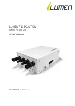
Page 1: ...ILUMEN PID SOLUTION ILUMEN PID BOX MINI INSTALLATION MANUAL Ilumen PID Box Mini Version 1 3...

Page 2: ...rostatic discharge 4 3 Scope of delivery 4 4 Product description 4 5 Mounting 4 5 1 Mounting location requirements 4 5 2 Mounting the Ilumen PID Box Mini 5 6 Electrical connections 5 6 1 Earth connect...

Page 3: ...PID Box Mini ensure that the permitted operating range of each component is maintained at all times Before using the Ilumen PID Box Mini you have to obtain the appropriate approval from the manufactu...

Page 4: ...nual 4 PRODUCT DESCRIPTION The Ilumen PID Box Mini is placed between the inverter and the solar array strings The power of the strings goes through the PID Box entering on one side and leaving on the...

Page 5: ...ion is to have a single outlet with a single circuit breaker of 16A 6 1 EARTH CONNECTION To receive the best result the frames of the solar modules must be connected to the earth connector of the Ilum...

Page 6: ...be terminated with a corresponding sealing plug Attention If you work with inverters with multiple MPPT s you cannot mix the PV arrays from multiple MPPT s Attention The maximum current that can pass...

Page 7: ...e To start up the Ilumen PID Box Mini plug in the DC power supply into a standard EU outlet This outlet must be on at all times Next see if the LED light on the Ilumen PID Box Mini starts burning Afte...

Page 8: ...to the frames of the PV modules and check the interconnections between the PV casings 4 Disconnect the PV array cables from the inverter 5 Connect the PV array cables to the Ilumen PID Box Mini inputs...

Page 9: ...connectors going to the PV arrays and then disconnect the lines going to the inverter When all electrical connections are disconnected you can dismount the Ilumen PID Box Mini 10TROUBLESHOOTING 10 1...

Page 10: ...n standby operation 0 2 W Typical power consumption in operation 8 W Maximum power consumption 20 W General data Dimensions W x D x H 263 x 140 x 72 mm Weight 1 440 g Operating temperature range 25 to...

Page 11: ...Ilumen 11 Installation Manual Ilumen PID Box Mini v1 3 12CONTACT Ilumen bvba Ambachtsstraat 19 3980 Tessenderlo Belgium Tel 32 13 30 61 77 info ilumen be www ilumen be...

Reviews: