background image

Ilumen 


16


Installation Manual Ilumen PIDbox Light v1.2 


RED FAST BLINKING

: power supply connected but no active solar system 

detected 


BLUE BLINKING

: active solar system detected and waiting for activation (30          

minutes waiting period.) This is normal startup behavior. 


BLUE CONTINIOUS: 

active solar system detected and activated, ready for curing  

at night 


GREEN BLINKING

: all startup conditions are met and PIDbox Light will start in 

less than 30 minutes 


RED

: PIDbox Light active at night time 


PURPLE: 

(OUTDOOR only) purple led can burn at night time. May switch to 

RED


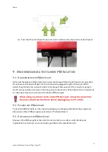
It is normal for the LED to be out at the beginning and at the end of the night 

After start-up you may turn the DC switch of the inverter back on, followed by the AC side of the 
PV plant. 

8


I

NSTALLATION SUMMARY


1)


Take the necessary safety precautions (AC side of the PV plant off and DC switch of the 
inverter off). 

2)


Mount the Ilumen PIDbox Light on a flat surface or if not available mount it correctly to a 
wall using the wall bracket. 

3)


Connect the Ilumen PIDbox Light earth pin to the frames of the PV modules and check 
the interconnections between the PV casings. 

4)


Disconnect the PV array cables from the inverter. 


5)


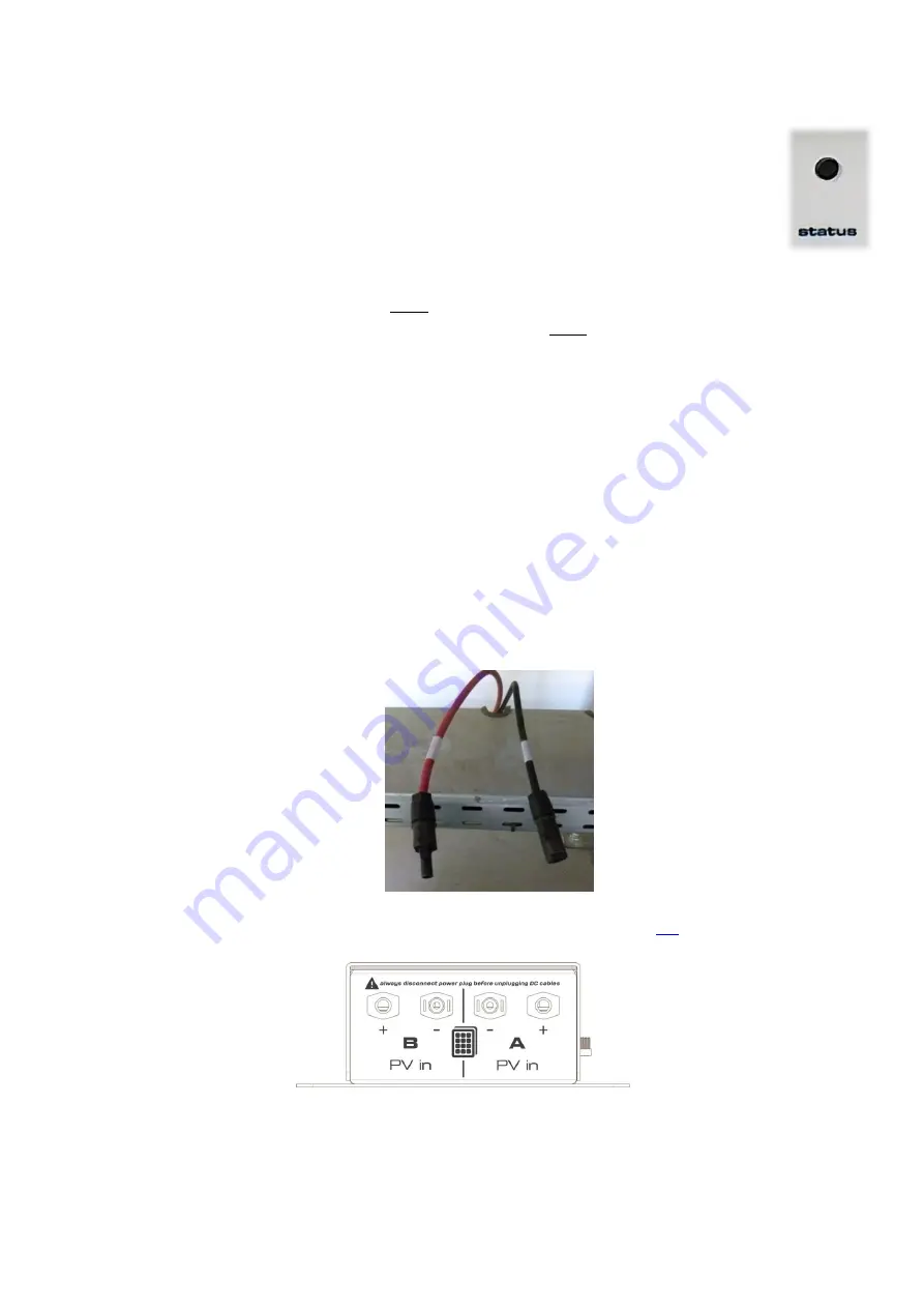
Connect the PV array cables to the Ilumen PIDbox Light inputs (se

6.2

 for details). 


6)


Connect the DC power supply to the Ilumen PIDbox Light. 

7)


Plug the DC power supply into an outlet (LED of the Ilumen PIDbox Light lights up if the 
PVs are producing electricity) 

Summary of Contents for PIDBOX

Page 1: ...ILUMEN PID SOLUTION ILUMEN PIDBOX LIGHT INSTALLATION MANUAL Ilumen PIDbox Light Version 1 1 INDOOR OUTDOOR...

Page 2: ...unting the Ilumen PIDbox Light using the wall brackets 6 6 Electrical connections 8 6 1 Earth connection 8 6 2 Solar array and inverter MPPT connections 8 6 3 Connecting the solar modules 10 6 3 1 Usi...

Page 3: ...men 3 Installation Manual Ilumen PIDbox Light v1 2 10 1 Faults 18 10 2 No good PID regeneration 18 10 3 Resetting the PIDbox Light 18 10 4 Repairing the PIDbox Light 18 11 Contact 19 12 Technical data...

Page 4: ...ates a hazardous situation which if not avoided will result in death or serious injury Information that is important for a specific topic or objective but is not safety relevant 2 SAFETY 2 1 APPROPRIA...

Page 5: ...PV plant switch off the Ilumen PIDbox Light When you want to change the arrangement of the Ilumen PIDbox Light you must switch off the Ilumen PIDbox Light 20 minutes prior to making any changes 2 3 2...

Page 6: ...f the PIDbox Light is on a flat surface Special rubber feet can be placed under the PIDbox Light to prevent scratching of any surface Usage of the wall brackets of the Ilumen PIDbox Light is needed wh...

Page 7: ...ht v1 2 2 Drill the holes 3 Insert the wall plugs if necessary 4 Screw the Ilumen PIDbox Light to the mounting surface and make sure adequate washers are installed Make sure the DC power plug is point...

Page 8: ...of all solar modules are at the earth potential if necessary you have to interconnect the mounting structures with additional cables 6 2 SOLAR ARRAY AND INVERTER MPPT CONNECTIONS When installing the...

Page 9: ...inverters with multiple MPPT s you cannot mix the PV arrays from multiple MPPT s The maximum amount of PV power that can be attached to 1 PIDbox Light is 100kWp This is the total of panels attached t...

Page 10: ...in the sections below 6 3 1 USING SPLITTER CABLES With the use of a splitter 1 to 2 you can simply hook up your PIDbox Light Simply detach a string from the 1st MPPT Insert the splitter the end with 1...

Page 11: ...Ilumen 11 Installation Manual Ilumen PIDbox Light v1 2 If you have an inverter with only 1 MPPT you can use following hook up scheme This way you will have 1 open input free for another inverter...

Page 12: ...the 1st MPPT of the inverter Then plug in the PV in A side of the PIDbox Light to the negative open input of the 1st MPPT of the inverter Repeat these steps for the 2nd MPPT Attach these cables to the...

Page 13: ...and have a breaking current of 2Amps The fuseholder also has to be rated 1000VDC Each input of the PIDbox Light must be protected by a fuse of 2Amps The second way is to place a cable connector with f...

Page 14: ...on Don t connect the AC side until commissioning Make sure that locking nut of the DC power plug for the outdoor version is tightened for insuring a waterproof product Make sure you always mount the p...

Page 15: ...ate 6x5mA 30 mA Always place the PIDbox Light behind a 300mA RCD to make sure the RCD is not tripped because of the leakage current of the PIDbox Light Also limit the number of PIDboxes to 60 devices...

Page 16: ...e end of the night After start up you may turn the DC switch of the inverter back on followed by the AC side of the PV plant 8 INSTALLATION SUMMARY 1 Take the necessary safety precautions AC side of t...

Page 17: ...g to the PV arrays and then disconnect the lines going to the inverter When all electrical connections are disconnected you can dismount the Ilumen PIDbox Light When doing any kind of work on the PIDb...

Page 18: ...night Product does not work If you connected the PIDbox when it was already dark outside the PIDbox will not become active during that 1st night Normally the PIDbox Light should work the nights after...

Page 19: ...ion Manual Ilumen PIDbox Light v1 2 Always contact iLumen technical service if your PIDbox Light is broken 11CONTACT Ilumen bvba Ambachtsstraat 19 3980 Tessenderlo Belgium Tel 32 13 30 61 77 info ilum...

Page 20: ...Operating temperature range 25 to 60 C 13 to 140 F Environmental conditions Indoor version IP30 indoor use only Outdoor version IP65 indoor outdoor use power supply IP30 PV connectors MC4 Configurati...

Reviews: