


Ilumen
20
Installation Manual Ilumen PIDbox Light v1.2
12
T
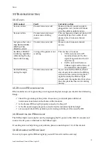
ECHNICAL DATA
Technical data
ILUMEN PIDBOX LIGHT
PV array / inverter input
Input PV voltage range
80 - 1000 V
Output voltage to ground
Up to 1000 V
Maximum total PV power
100 kWp (c-Si)
Maximum output current in operation
5 mA
GRID (AC)
Nominal AC voltage
100 to 240 V
Nominal AC grid frequency
47 to 63 Hz
Power consumption in standby operation
< 0.2 W
Typical power consumption in operation
8 W
Maximum power consumption
20 W
General data
Dimensions (W x D x H)
270 x 200 x 75 mm
Weight
1.100 g
Operating temperature range
-25 to 60 °C (-13 to 140 °F)
Environmental conditions
Indoor version - IP30 - indoor use only
Outdoor version - IP65
–
indoor / outdoor use (power supply IP30)
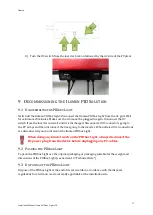
PV connectors
MC4
Configuration
Maximum two MPPT per PIDbox Light
Maximum one MPPT per input (A/B)
None of the connected solar module poles may become grounded
1 screw connection for grounding the frames of the PV modules
The inverter manufacturer’s approval is needed to place the PIDbox LIGHT
The client is responsible for getting the approval
This product will function with p-type solar cells.
If you want to apply this product to another technology, please contact iLumen
Various
Warranty
Up to 20 years
Certificates
www.ilumen.be
Registration before use
www.myilumen.be


