55
OPERATION / USER
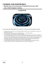
To preserve the quality of the nano coating please observe these guidelines.
• Allow the burners to cool down to room temperature before cleaning. Do not dip them
in cold water to speed up the cooling down process.
• Wash with warm, soapy water. Rub with a soft cloth or non-abrasive sponge. Do not
use abrasive powder, steel wool or abrasive sponges.
• Avoid leaving food or splatter on the burner. This will result in charred deposits that will
be more difficult to remove and may cause stains or discolourations to appear on the
surface. These blemishes do not alter the functionality of the product. In some cases
they can be eliminated by immersing the burners in hot, soapy water and then wiping
them gently with a soft cloth or non-abrasive sponge. For stubborn stains, use warm
white vinegar and wiping them as above.
• Avoid leaving the burners in contact with food for a long time, especially if acidic, such
as tomato sauce, lemon juice.
• Avoid contact with metal objects; if you must touch them, use wooden or plastic
utensils.
• Avoid washing in the dishwasher, the underside of the burner is not coated and would
get irreparably damaged.
• In case of malfunction, make sure that the holes in the outer crown are perfectly dry
and clean.
Annual service by an authorised person is recommended, or if any of the following
conditions are noticed. Incomplete ignition, appreciable yellow tipping, carbon
deposition, lifting, floating, lighting back or objectionable odour.
Contact 1300 856 411 or customercare@eurolinx.com.au
ATTENTION:
CLEANING AND MAINTENANCE
– Maintenance and cleaning of total black burners with
nano-technological coating
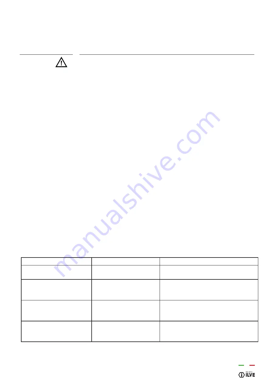
Problem
Cause
Solution
The flame is uneven /
unstable
Wrong gas type
Have an expert check the gas supply
The flame from the burners
suddenly changes
Wrongly assembled burner
parts
Ensure burner parts are in the correct
position
Burner extinguishes after
lighting
Insufficient time for the
sensor to detect that the
burner is on
Push the burner knob a little longer (no
more than 10 seconds)
Spark is uneven
Food residues between
the electrode and the
burner
Make sure both the burner components
and the ignition electrode are clean
Summary of Contents for MAJESTIC Series
Page 3: ......
Page 4: ......
Page 73: ...INSTALLATION 73 ADJUSTMENTS Adjustments minimun GAS flow Fig C2 ...
Page 76: ...76 HOB GAS BASIC INDUCTION HOB AREA 5 WIRING DIAGRAM ...
Page 77: ...INSTALLATION 77 WIRING DIAGRAM P09I E3 INDUCTION HOB AREA 4 ...
Page 78: ...78 INDUCTION HOB AREA 5 INDUCTION HOB AREA 6 WIRING DIAGRAM ...
Page 79: ...INSTALLATION 79 WIRING DIAGRAM P 06 07 30 08 09 E3 K L 06 09 MP ...
Page 80: ...80 WIRING DIAGRAM P 06 07 30 08 09 H3 P 06 07 30 08 09 G3 ...
Page 81: ...INSTALLATION 81 WIRING DIAGRAM M 07 30 09 E3 M 07 30 09 H3 ...
Page 82: ...82 WIRING DIAGRAM M09I E3 M09I H3 ...
Page 83: ...INSTALLATION 83 WIRING DIAGRAM KD LD 09 10 MP LD 09 10 G3 ...
Page 84: ...84 WIRING DIAGRAM M12I H3 M12 E3 ...
Page 85: ...INSTALLATION 85 M12 H3 M12I E3 WIRING DIAGRAM ...
Page 86: ...86 M15 E3 M15 H3 WIRING DIAGRAM ...
Page 87: ...INSTALLATION 87 MD10 E3 MD10 H3 WIRING DIAGRAM WIRING DIAGRAM ...
Page 88: ...88 MD10I E3 MD10I H3 WIRING DIAGRAM WIRING DIAGRAM ...
Page 89: ...INSTALLATION 89 MD12I E3 MD12I H3 WIRING DIAGRAM ...
Page 90: ...90 MD12 E3 MD12 H3 WIRING DIAGRAM ...
Page 91: ...INSTALLATION 91 WIRING DIAGRAM WIRING DIAGRAM P12 IE3 P12 IH3 ...
Page 92: ...92 WIRING DIAGRAM WIRING DIAGRAM P12 E3 P12 H3 ...
Page 93: ...INSTALLATION 93 P15 PD12 E3 P15 PD12 H3 WIRING DIAGRAM ...
Page 94: ...94 PD 09 10 I E3 PD 09 10 E3 WIRING DIAGRAM ...
Page 95: ...INSTALLATION 95 PD LD 09 10 H3 PD LD 09 10 I H3 WIRING DIAGRAM ...
Page 96: ...96 PD12I E3 PD12I H3 WIRING DIAGRAM ...
Page 97: ...97 OPERATION USER NOTES ...
Page 98: ...98 NOTES ...
Page 102: ......


