INSTALLATION
65
This appliance must be installed by an authorised person in accordance with this instruction manual, AS/NZS 5601
– Gas installations (installation and pipe sizing), local gas fitting regulations, local electrical regulations, local water
regulations, local health regulations, Building Code of Australia and any other government authority.
This appliance is suitable for connection with rigid pipe or flexible hose. The isolating manual shut-off valve connection
point must be accessible when the appliance is installed. Flexible hose assembly must be certified to AS/NZS 1869
class B or D, be of appropriate internal diameter for the total gas consumption, be kept as short as possible (not ex-
ceeding 1200mm), must not be in contact with the floor or any hot or sharp surfaces. The hose assembly must not be
subject to strain, abrasion, kinking or deformation.
Natural Gas: the supplied regulator must be fitted to the appliance inlet connection. Gas pressure must be adjusted to
1.0 kPa when approximately 50% of the burners are on high flame, the appliance test point is located on the regulator.
ULPG: the supplied test point adaptor must be fitted to the appliance inlet connection. Gas pressure must be adjusted
to 2.75 kPa, the appliance test point is located on the test point adaptor.
Gas leakage and operation of the appliance must be tested by the installer before leaving. Check burner flames are
blue in colour, stable and completely ignite at both high and low flame settings with no appreciable yellow tipping,
carbon deposition, lifting, floating, lighting back or objectionable odour. Test burners individually and in combination,
When satisfied with the operation of the cooker, please instruct the user on the correct method of operation.
Where the data plate is obscured by cabinetry when the cooker is in the installed position, place the supplied duplicate
data plate to a suitable
adjacent surface or within the instruction manual for future reference.
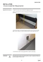
INSTALLATION
- Installation of the cooker
Any maintenance operation, etc. It must be carried out by an authorized technician
after disconnecting the appliance from the mains and closing the gas supply.
ATTENTION
Summary of Contents for MAJESTIC Series
Page 3: ......
Page 4: ......
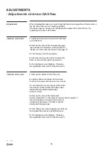
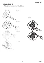
Page 73: ...INSTALLATION 73 ADJUSTMENTS Adjustments minimun GAS flow Fig C2 ...
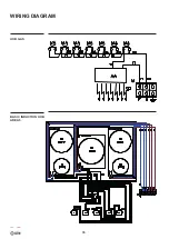
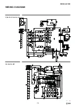
Page 76: ...76 HOB GAS BASIC INDUCTION HOB AREA 5 WIRING DIAGRAM ...
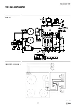
Page 77: ...INSTALLATION 77 WIRING DIAGRAM P09I E3 INDUCTION HOB AREA 4 ...
Page 78: ...78 INDUCTION HOB AREA 5 INDUCTION HOB AREA 6 WIRING DIAGRAM ...
Page 79: ...INSTALLATION 79 WIRING DIAGRAM P 06 07 30 08 09 E3 K L 06 09 MP ...
Page 80: ...80 WIRING DIAGRAM P 06 07 30 08 09 H3 P 06 07 30 08 09 G3 ...
Page 81: ...INSTALLATION 81 WIRING DIAGRAM M 07 30 09 E3 M 07 30 09 H3 ...
Page 82: ...82 WIRING DIAGRAM M09I E3 M09I H3 ...
Page 83: ...INSTALLATION 83 WIRING DIAGRAM KD LD 09 10 MP LD 09 10 G3 ...
Page 84: ...84 WIRING DIAGRAM M12I H3 M12 E3 ...
Page 85: ...INSTALLATION 85 M12 H3 M12I E3 WIRING DIAGRAM ...
Page 86: ...86 M15 E3 M15 H3 WIRING DIAGRAM ...
Page 87: ...INSTALLATION 87 MD10 E3 MD10 H3 WIRING DIAGRAM WIRING DIAGRAM ...
Page 88: ...88 MD10I E3 MD10I H3 WIRING DIAGRAM WIRING DIAGRAM ...
Page 89: ...INSTALLATION 89 MD12I E3 MD12I H3 WIRING DIAGRAM ...
Page 90: ...90 MD12 E3 MD12 H3 WIRING DIAGRAM ...
Page 91: ...INSTALLATION 91 WIRING DIAGRAM WIRING DIAGRAM P12 IE3 P12 IH3 ...
Page 92: ...92 WIRING DIAGRAM WIRING DIAGRAM P12 E3 P12 H3 ...
Page 93: ...INSTALLATION 93 P15 PD12 E3 P15 PD12 H3 WIRING DIAGRAM ...
Page 94: ...94 PD 09 10 I E3 PD 09 10 E3 WIRING DIAGRAM ...
Page 95: ...INSTALLATION 95 PD LD 09 10 H3 PD LD 09 10 I H3 WIRING DIAGRAM ...
Page 96: ...96 PD12I E3 PD12I H3 WIRING DIAGRAM ...
Page 97: ...97 OPERATION USER NOTES ...
Page 98: ...98 NOTES ...
Page 102: ......


