O P E R A T I O N S
Front Panel Overview
02_03
LDC-3926339
11
C H A P T E R
2
contact information) for information about Tech Notes and other support
information.
Photodiode Connections
Many laser diode modules contain an internal photodiode that monitors the back-
facet emission of the laser. Usually, this photodiode is internally connected to
either the laser anode or cathode.
The photodiode and laser connections to the LDC-3926339 are electrically
isolated from ground and each other. If a 4-pin connection is made (no common
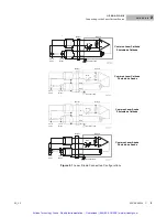
connections) no additional jumpers are required. Figure 2.1 on page
9
shows the
recommended connections and shielding for 3-pin lasers (where the common
connection is internal to the device). A 4-pin laser must be connected with the
same shielding as shown in Figure 2.1, but the common connection (between the
photodiode and the laser) is optional.
Grounding Considerations
The laser output of the LDC-3926339 is isolated from chassis ground allowing
either output terminal to be grounded at the user's option. Figure 2.1 shows the
proper earth-ground shielding for laser diode/photodiode connections.
Front Panel Overview
This section describes how to operate the LDC-3926339 from the front panel of
the LDC-3926 mainframe. For a more detailed explanation of the front panel keys,
see the LDC-3926 User's Guide.
General Front Panel Operation
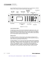
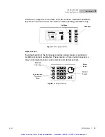
Figure 2.3 shows the front panel of the LDC-3926 mainframe. The key operating
parameters for the LDC-3926339 can be set, adjusted, and displayed through
established menus on the front panel. You control the menus on the display by
using the keys (pushbuttons) to the right of the display. There are two kinds of
Artisan Technology Group - Quality Instrumentation ... Guaranteed | (888) 88-SOURCE | www.artisantg.com


