7
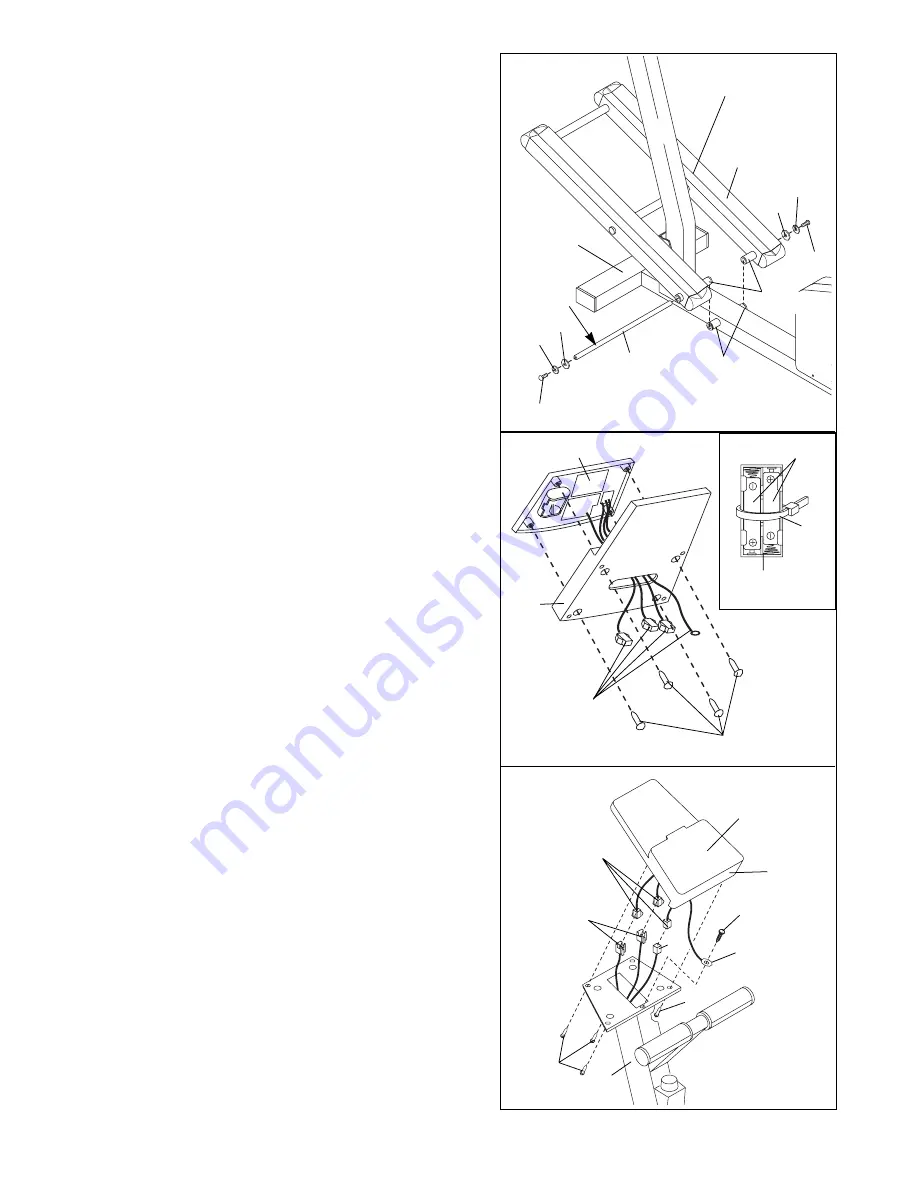
8. Connect the Extension Wire (51) to the corresponding
wire on the Console (87).
Next, connect the two Pulse Wires (86) to the two
remaining wires on the Console (87). Note: Either
Pulse Wire can be attached to either wire on the
Console.
Next, connect the ground wire to the indicated hole in
the Upright (2) with an M4 x 16mm Screw (35).
Carefully feed the wires down into the Upright (2).
Attach the Console Base (49) to the Upright with four
M4 x 16mm Screws (35).
Be careful to avoid pinch-
ing the wires.
8
86
87
49
35
35
2
51
Console
Wires
35
Ground Wire
7. The Console (87) requires two ÒAAÓ batteries (not
included). Alkaline batteries are recommended. To
install batteries, turn the console over and insert two
batteries into the battery clip as shown in the inset
drawing.
Make sure that the negative ends of the
batteries (marked ÒÑÓ) are touching the springs in
the battery clip.
Attach a Plastic Tie (53) to the battery clip as shown.
Attach the Console (87) to the Console Base (49) with
four M4 x 16mm Screws (35), making sure that the
indicated wires are extending from the Console Base
(49).
Be careful not to pinch the wires.
7
35
Wires
Battery
Clip
Batteries
87
49
53
6
5
V-shaped Groove
29
Grease
81
81
30
30
58
58
1
Tubes
Tubes
6. Slide an M8 Split Washer (58) and an M8 Washer (81)
onto an Axle Screw (30). Tighten the Axle Screw into
one end of the Incline Axle (29). Next, apply a small
amount of the included grease to the Incline Axle.
Align the indicated tubes on the Incline Frame (5) with
the tubes on the Base (1).
Make sure that the Incline
Frame is turned so the V-shaped grooves are on
top.
Insert the Incline Axle (29) through the Incline
Frame and the Base. Note: It may be helpful to tap the
Incline Axle with a rubber mallet to insert it.
Slide an M8 Split Washer (58) and an M8 Washer (81)
onto the other Axle Screw (30). Tighten the Axle Screw
into the open end of the Incline Axle (29).
Summary of Contents for Image 2.2E
Page 17: ...17 NOTES ...


