background image

7

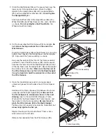
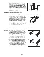
2. Orient the Right Upright (36) so the square hole near the

lower end is in the position shown. Attach the Right
Upright to the Upright Base (48) with two Upright Bolts
(40) and two Upright Star Washers (39). 

Do not tighten

the Upright Bolts yet.

Attach each Wheel (45) to the Upright Base (48) with a
Wheel Bolt (89), two Wheel Spacers (44), and a Nut (47)
as shown. 

Do not overtighten the Wheel Bolts; 

the

Wheels should turn freely.

48

Square Hole

45

47

44

89

45

44

36

44

89

47

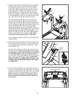
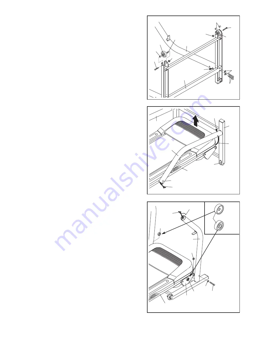
3. Cut the tie securing the Wire Harness (28) in a bundle. 

Do

not remove the large colored tie on the end of the
Wire Harness.

Orient the Upright Base (48) so the Wheels (45) are at the
bottom. Next, position the Upright Base and the Uprights
(31, 36) around the frame assembly as shown. 

Have another person lift the front of the frame assembly
and hold it. Insert the Wire Harness (28) into the square
hole near the lower end of the Right Upright (36) and out
of the top. Next, raise the Uprights (31, 36) so the Upright
Base (48) is flat on the floor. 

Make sure that the end of

the Wire Harness does not fall into the Right Upright;
it may be helpful to hold the colored tie on the end of
the Wire Harness.

28

Colored Tie

48

28

36

31

45

3

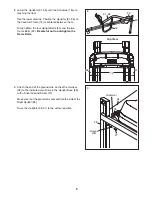
4. Open the included grease packet, and apply equal

amounts of grease to both sides of each Frame Spacer
(34).

Hold one of the Frame Spacers (34) between the frame
assembly and the Right Upright (36); 

make sure that

the Frame Spacer is oriented as shown in the inset
drawing.

Insert a Frame Bolt (32) through a Frame

Washer (33), the Right Upright, the Frame Spacer, and
the bracket on the frame assembly. 

Be careful not to

pinch the Wire Harness (28) in the Right Upright.

Tighten a Nut (47) several turns onto the Frame Bolt, but

do not fully tighten the Nut yet.

Repeat this step on the left side. Note: There is not a
wire harness on the left side.

Remove the colored tie from the Wire Harness (28).

Frame Assembly

Frame Assembly

Hole

32

59

34

34

33

4

47

28

36

Right

Side

Left

Side

34

40

39

Colored Tie

2

Summary of Contents for 17.0 R Treadmill

Page 1: ...MANUAL QUESTIONS As a manufacturer we are com mitted to providing complete customer satisfaction If you have questions or if parts are damaged or missing PLEASE CONTACT OUR CUSTOMER SERVICE DEPARTMEN...

Page 2: ...ENT 11 HOW TO FOLD AND MOVE THE TREADMILL 17 TROUBLESHOOTING 19 CONDITIONING GUIDELINES 21 HOW TO ORDER REPLACEMENT PARTS Back Cover LIMITED WARRANTY Back Cover Note An EXPLODED DRAWING and a PART LIS...

Page 3: ...your local electronics store 12 Failure to use a properly functioning surge suppressor could result in damage to the con trol system of the treadmill If the control sys tem is damaged the walking belt...

Page 4: ...readmill in a commer cial rental or institutional setting WARNING Before beginning this or any exercise program consult your physician This is especially important for persons over the age of 35 or pe...

Page 5: ...the product model number and serial number before calling The model number of the treadmill is IMTL49105 0 The serial number can be found on a decal attached to the tread mill see the front cover of...

Page 6: ...own phillips screwdriver rubber mallet adjustable wrench and wire cutters For help identifying the assembly hardware see the drawings below If a part is not in the parts bag check to see if it has bee...

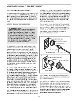
Page 7: ...Right Upright 36 and out of the top Next raise the Uprights 31 36 so the Upright Base 48 is flat on the floor Make sure that the end of the Wire Harness does not fall into the Right Upright it may be...

Page 8: ...ight Handrail 18 the Latch Housing 30 is attached to the left Handrail Next identify the Right Handrail Endcap 92 which has an R near the two screw holes Slide the Right Handrail Endcap onto the right...

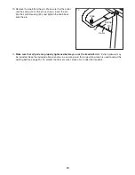
Page 9: ...40 and the two Frame Bolts 32 Be careful not to overtighten the Frame Bolts 31 31 36 32 18 74 36 Top View 8 40 9 Attach the end of the ground wire on the Wire Harness 28 to the indicated small hole in...

Page 10: ...a secure place the large allen wrench is used to adjust the walking belt see page 20 To protect the floor or carpet place a mat under the treadmill 10 Remove the knob from the pin Make sure that the...

Page 11: ...alfunc tion or break down grounding provides a path of least resistance for electric current to reduce the risk of elec tric shock This product is equipped with a cord having an equipment grounding co...

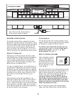
Page 12: ...tent position on the treadmill as you walk Lighter users may also find it helpful to reduce the incline of the treadmill or to increase the speed of the walking belt Trainer Programs The console also...

Page 13: ...treadmill as desired To change the incline of the treadmill press the Incline increase and decrease buttons Each time a button is pressed the incline setting will change by 0 5 if a button is held do...

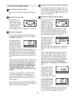
Page 14: ...ord HOW TO USE THE MYTRACKS STEPCOUNTER PROGRAM Insert the key into the console See HOW TO TURN ON THE POWER on page 12 Select the MyTracks StepCounter program Press the 10 000 Steps Program button a...

Page 15: ...ow long the program will last A profile of the speed settings of the pro gram will scroll across the matrix in the upper right corner of the display Press the Start button or the Speed increase button...

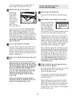
Page 16: ...ttings for the next period To end the program press the Stop button remove the key and then reinsert the key Follow your progress with the display See step 5 on page 13 Measure your heart rate if desi...

Page 17: ...il the catch passes the latch pin and then slowly release the latch knob Make sure that the catch is held securely by the latch pin as shown To protect the floor or carpet from damage place a mat unde...

Page 18: ...wn until the frame is past the latch pin 2 Hold the metal frame firmly with both hands and lower the treadmill to the floor CAUTION To decrease the possibility of injury do not lower the treadmill by...

Page 19: ...e switch protrudes as shown the circuit breaker has tripped To reset the circuit breaker wait for five minutes and then press the switch back in PROBLEM The power turns off during use SOLUTION a Check...

Page 20: ...insert the key and run the treadmill for a few minutes Repeat until the walking belt is properly tightened c If the walking belt still slows when walked on see the front cover of this manual PROBLEM...

Page 21: ...that requires large amounts of oxygen for prolonged periods of time This increases the demand on the heart to pump blood to the muscles and on the lungs to oxygenate the blood For aerobic exercise ad...

Page 22: ...Stretch With one leg in front of the other reach forward and place your hands against a wall Keep your back leg straight and your back foot flat on the floor Bend your front leg lean forward and move...

Page 23: ...23 NOTES...
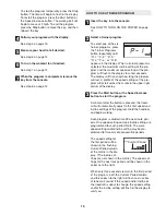
Page 24: ...ing Decal 44 4 Wheel Spacer 45 2 Wheel 46 1 Pulley Flywheel 47 4 Nut 48 1 Base 49 2 Clamp 50 1 Belly Pan 51 1 Controller 52 2 Lift Frame Washer 53 2 Lift Frame Bolt 54 5 3 8 Nut 55 1 Lift Motor 56 1 S...

Page 25: ...44 47 37 38 47 44 45 44 89 2 49 23 29 50 51 2 38 38 38 56 47 54 54 55 60 54 61 54 66 64 54 65 66 72 73 4 4 3 71 68 70 69 4 4 78 78 38 76 83 38 81 82 85 84 11 82 81 79 80 38 76 4 4 74 75 4 68 4 69 70 1...

Page 26: ...damages arising out of or in con nection with the use or performance of the product or damages with respect to any economic loss loss of property loss of revenues or profits loss of enjoyment or use...

Reviews: