background image

12

OPERATION AND ADJUSTMENT

THE PRE-LUBRICATED WALKING BELT

Your treadmill features a walking belt coated with high-
performance lubricant. 

IMPORTANT: Never apply sil-

icone spray or other substances to the walking
belt or the walking platform. Such substances will
deteriorate the walking belt and cause excessive
wear.

HOW TO PLUG IN THE POWER CORD 

Your treadmill, like any other type of sophisticated
electronic equipment, can be seriously damaged by
sudden voltage changes in your home’s power.
Voltage surges, spikes, and noise interference can 
result from weather conditions or from other appliances
being turned on or off. 

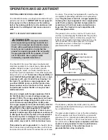
To decrease the possibility of

your treadmill being damaged, always use a surge
suppressor with your treadmill (see drawing 1 at
the right). To purchase a surge suppressor, see
your local IMAGE dealer or call the toll-free tele-
phone number on the front cover of this manual
and order part number 146148, or see your local
electronics store.

Use only a single-outlet surge suppressor that is
UL 1449 listed as a transient voltage surge sup-
pressor (TVSS). The surge suppressor must have a
UL suppressed voltage rating of 400 volts or less
and a minimum surge dissipation of 450 joules.
The surge suppressor must be electrically rated for
120 volts AC and 15 amps. There must be a moni-
toring light on the surge suppressor to indicate
whether it is functioning properly. Failure to use a
properly functioning surge suppressor could result
in damage to the control system of the treadmill. If
the control system is damaged, the walking belt
may change speed, accelerate or stop unexpect-
edly, which may result in a fall and serious injury.

This product must be grounded. 

If it should malfunc-

tion or break down, grounding provides a path of least
resistance for electric current to reduce the risk of elec-

tric shock. This product is equipped with a cord having
an equipment-grounding conductor and a grounding
plug. 

Plug the power cord into a surge suppressor,

and plug the surge suppressor into an appropriate
outlet that is properly installed and grounded in
accordance with all local codes and ordinances.
Important: The treadmill is not compatible with
GFCI-equipped outlets.

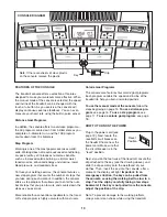
This product is for use on a nominal 120-volt circuit,
and has a grounding plug that looks like the plug illus-
trated in drawing 1 below. A temporary adapter that
looks like the adapter illustrated in drawing 2 may be
used to connect the surge suppressor to a 2-pole 
receptacle as shown in drawing 2 if a properly 
grounded outlet is not available. 

The temporary adapter should be used only until a
properly grounded outlet (drawing 1) can be installed
by a qualified electrician. 

The green-colored rigid ear, lug, or the like extending
from the adapter must be connected to a permanent
ground such as a properly grounded outlet box cover.
Whenever the adapter is used it must be held in place
by a metal screw. 

Some 2-pole receptacle outlet box

covers are not grounded. Contact a qualified elec-
trician to determine if the outlet box cover is
grounded before using an adapter.

DANGER:

Improper connection

of the equipment-grounding conductor can
result in an increased risk of electric shock.
Check with a qualified electrician or service-
man if you are in doubt as to whether the
product is properly grounded. Do not modify
the plug provided with the product—if it will
not fit the outlet, have a proper outlet 
installed by a qualified electrician.

1

2

Grounded Outlet Box

Grounded Outlet Box

Grounding Plug

Surge Suppressor

Surge Suppressor

Grounding Pin

Adapter

Lug

Metal Screw

Grounded Outlet

Grounding Pin

Summary of Contents for 17.5 S IMTL49606.0

Page 1: ...EE 1 800 753 4645 Mon Fri 6 a m 6 p m MST Sat 8 a m 5 p m MST ON THE WEB www iconservice com Visit our website at www weslo com new products prizes fitness tips and much more Visit our website at www...

Page 2: ...ENT 12 HOW TO FOLD AND MOVE THE TREADMILL 20 TROUBLESHOOTING 21 CONDITIONING GUIDELINES 23 HOW TO ORDER REPLACEMENT PARTS Back Cover LIMITED WARRANTY Back Cover Note An EXPLODED DRAWING and a PART LIS...

Page 3: ...described on page 12 To purchase a surge suppressor see your local IMAGE dealer or call the toll free telephone number on the front cover of this manual and order part number 146148 or see your local...

Page 4: ...representative Servicing other than the procedures in this manual should be performed by an authorized ser vice representative only 25 This treadmill is intended for in home use only Do not use this...

Page 5: ...you note the product model number and serial number before calling The model number of the treadmill is IMTL49606 0 The serial number can be found on a decal attached to the tread mill see the front c...

Page 6: ...The number in parentheses below each drawing is the key number of the part from the PART LIST in the center of the manual The number following the parentheses is the quantity used in assembly To avoi...

Page 7: ...it to the Base 48 with two Upright Bolts 27 and two Upright Star Washers 39 do not tighten the Upright Bolts yet 48 27 27 39 39 31 Bend Large Hole Bend 2 4 Set the Base 48 near the front of the tread...

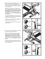
Page 8: ...it to the position shown Pull gently on the upper end of the Upright Wire 28 to remove any excess slack Cut the plastic tie and remove the strap from the Upright Wire 28 5 36 91 32 32 34 34 33 47 47...

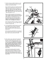
Page 9: ...rail 18 and out of the indi cated square hole If necessary grip the con nector with needlenose pliers only in the area indicated by the arrow see the inset drawing Then attach the ground wire to the H...

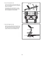
Page 10: ...27 and the Frame Bolts 32 on each side of the treadmill Do not overtighten the Frame Bolts 36 31 36 32 74 74 31 View from Above Side View 10 27 11 Raise the Uprights 31 36 Rotate the Left and Right B...

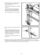
Page 11: ...n into the Latch Sleeve 30 and the Left Upright 31 Press the Latch Insert 89 into the other side of the Left Upright and then tighten the knob back onto the pin Remove the plastic packaging from the b...

Page 12: ...alfunc tion or break down grounding provides a path of least resistance for electric current to reduce the risk of elec tric shock This product is equipped with a cord having an equipment grounding co...

Page 13: ...exercise More reliable than conventional pedometers the tread mill s step program is highly accurate with most users Calorie Goal Programs The console also features four calorie goal programs Each pro...

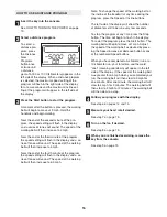
Page 14: ...to flash in the display To restart the walking belt press the Start button the Speed increase button or one of the numbered speed buttons Note The first time you use the treadmill periodi cally inspec...

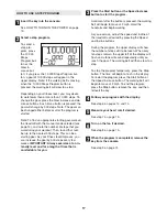
Page 15: ...r the most accurate heart rate reading continue to hold the contacts for at least 15 seconds Turn on the fan if desired To turn on the fan at low speed press the Fan button the word Low will appear in...

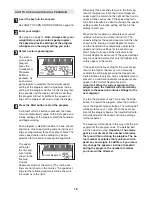
Page 16: ...ones will sound The speed of the walking belt will then increase to 6 5 mph Note To change the speed of the walking belt or the incline of the treadmill at any time during the program press the Speed...

Page 17: ...ps every few weeks IMPORTANT Always exercise at an in tensity level and for a length of time that is comfortable for you Press the Start button or the Speed increase button to start the program A mome...

Page 18: ...d and or in cline of the treadmill is about to change the speed setting and or the incline setting will flash in the display to alert you When the first segment is completed all speed settings will mo...

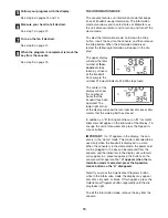
Page 19: ...hours that the treadmill has been operated The lower right corner of the display will show the total number of miles or kilo meters that the walking belt has moved In addition an E for English miles...

Page 20: ...not leave the treadmill in the storage position in temperatures above 85 Fahrenheit HOW TO MOVE THE TREADMILL Before moving the treadmill convert it to the storage position as described above Make su...

Page 21: ...a Check the circuit breaker located on the treadmill frame near the power cord see the drawing above If the circuit breaker has tripped wait for five minutes and then press the switch back in b Make s...

Page 22: ...clockwise 1 2 of a turn if the walking belt has shifted to the right turn the left bolt counterclockwise 1 2 of a turn Be careful not to overtighten the walking belt Then plug in the power cord inser...

Page 23: ...ctivity that requires large amounts of oxygen for prolonged periods of time This increases the demand on the heart to pump blood to the muscles and on the lungs to oxygenate the blood For aerobic exer...

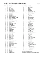
Page 24: ...ine Motor Nut Top 47 4 Nut 48 1 Base 49 3 Plastic Tie 50 1 Belly Pan 51 1 Controller 52 2 Upright Endcap 53 2 Lift Frame Bolt 54 6 3 8 Nut 55 1 Lift Motor 56 1 Stop Bracket 57 1 Incline Motor Bolt Top...

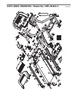
Page 25: ...8 38 38 56 47 54 46 55 60 54 54 11 62 61 54 66 24 64 65 66 72 73 4 4 3 71 68 4 4 78 78 38 76 83 38 81 82 85 84 11 82 81 79 80 38 76 4 4 74 75 4 68 4 63 24 53 33 12 12 71 76 76 67 43 69 69 40 41 2 2 2...

Page 26: ...ial damages arising out of or in con nection with the use or performance of the product or damages with respect to any economic loss loss of property loss of revenues or profits loss of enjoyment or u...

Reviews: