background image

15

Inspect and properly tighten all parts of the elliptical
exerciser regularly. Replace any worn parts immedi-
ately. The elliptical exerciser can be cleaned with a
soft cloth and mild detergent. 

Do not use abrasives

or solvents. 

To prevent damage to the console, keep

liquids away from the console and keep the console
out of direct sunlight. 

When storing the elliptical exerciser, remove the bat-
teries from the console. Keep the elliptical exerciser in
a clean, dry location, away from moisture and dust.

CONSOLE TROUBLESHOOTING

If the console does not function properly, the batteries
should be replaced. To replace the batteries, see
assembly step 8 on page 8.  

HANDGRIP PULSE SENSOR TROUBLESHOOTING

If the handgrip pulse sensor does not function proper-
ly, make sure that your hands are positioned as
described in step 5 on page 12. Be careful not to
move your hands excessively or to squeeze the metal
contacts too tightly. For optimal performance, clean
the metal contacts using a soft cloth; 

never use alco-

hol, abrasives, or chemicals.

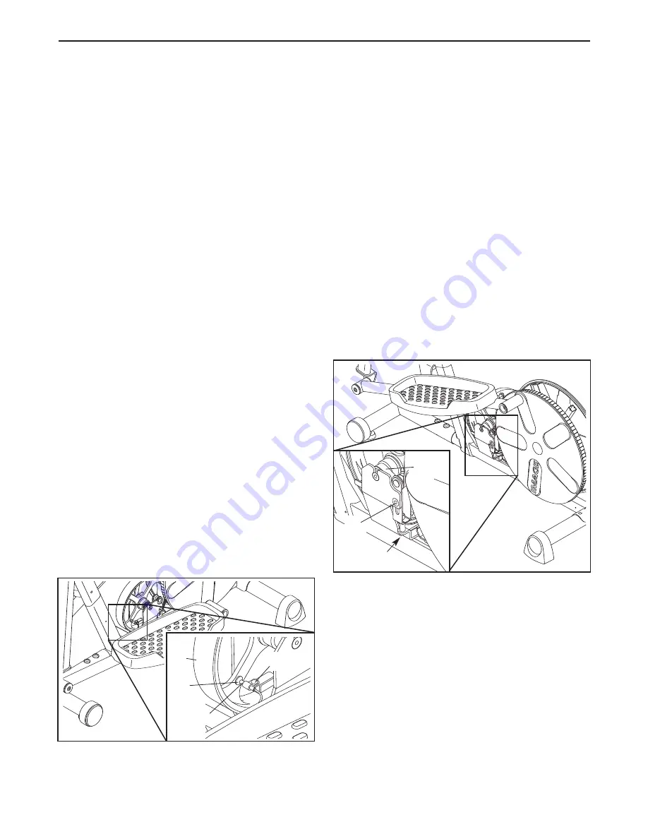
HOW TO ADJUST THE REED SWITCH

If the console does not display correct feedback, the
reed switch should be adjusted. First, remove all of
the screws from both side shields;

there are three

sizes of screws in the side shields—note which
size of screw you remove from each hole.

Next, locate the Reed Switch (47). Turn the Flywheel
(48) until the Magnet (53) is aligned with the Reed

Switch. Loosen, but do not remove, the indicated 
M4 x 16mm Screw (60). Slide the Reed Switch slight-
ly closer to or away from the Magnet, and then
retighten the Screw. Rock the Flywheel forward and
back just enough that the Magnet passes the Reed
Switch repeatedly. Repeat until the console displays
correct feedback. When the Reed Switch is correctly
adjusted, reattach the side shields. Note: If you have
questions regarding which screw should be in which
hole, see EXPLODED DRAWING B on page 19 and
the PART LIST on page 17.

HOW TO ADJUST THE BELT

If you can feel the pedals slip while you are pedaling,
even when the resistance of the pedals is at the high-
est setting, the Belt (37) may need to be adjusted.
First, remove all of the screws from both side shields;

there are three sizes of screws in the side
shields—note which size of screw you remove
from each hole.

Next, loosen the M8 x 19mm Flat Head Bolt (61) and
turn the Adjustment Screw (62) until the Belt (37) is
tight. Once the Belt is tight, tighten the Flat Head
Screw. Then, reattach the side shields. Note: If you
have questions regarding which screw should be in
which hole, see EXPLODED DRAWING B on page 19
and the PART LIST on page 17.

MAINTENANCE AND TROUBLESHOOTING 

48

53

60

47

61

37

62

Summary of Contents for 8.25 Elliptical

Page 1: ...45 Mon Fri 6 a m 6 p m MST Sat 8 a m 5 p m MST ON THE WEB www iconservice com Visit our website at www weslo com new products prizes fitness tips and much more Visit our website at www jumpking com ne...

Page 2: ...4 ASSEMBLY 5 HOW TO USE THE ELLIPTICAL EXERCISER 10 MAINTENANCE AND TROUBLESHOOTING 15 CONDITIONING GUIDELINES 16 PART LIST 17 EXPLODED DRAWING 18 ORDERING REPLACEMENT PARTS Back Cover LIMITED WARRAN...

Page 3: ...ercise clothes when using the elliptical exerciser Always wear athletic shoes for foot protection while exer cising 9 When mounting and dismounting the ellipti cal exerciser always hold the upper body...

Page 4: ...is manual To help us assist you note the product model number and serial number before con tacting us The model number is IMEL2305 1 The serial number can be found on a decal attached to the elliptica...

Page 5: ...he key number of the part from the PART LIST on page 17 The number following the key number is the quantity needed for assembly Note Some small parts may have been pre assembled If a part is not found...

Page 6: ...8 so the four posts see the inset drawing are facing away from the Front Stabilizer 3 Attach the Wheel to the Front Stabilizer with an M8 Nylon Locknut 59 Next press a Wheel Cover 29 onto the posts on...

Page 7: ...n apply a small amount of grease to two Wave Washers 27 While another person aligns the Upper Body Legs 6 with the Upright 2 as shown insert the Pivot Axle 16 into the Upper Body Legs and the Upright...

Page 8: ...f you do not do this the console displays or other electronic components may become damaged Remove the battery cover from the Console Insert four batteries into the Console make sure that the batterie...

Page 9: ...ighten an Arm Knob 11 onto the Carriage Bolt Attach the Right Upper Body Arm not shown to the right Upper Body Leg 6 in the same way 6 11 82 12 82 13 82 4 82 11 Make sure that all parts of the ellipti...

Page 10: ...loosen the arm knob Next slide the upper body arm to the desired position and then firmly retighten the arm knob Make sure that both upper body arms are at the same height HOW TO EXERCISE ON THE ELLI...

Page 11: ...rease your pedaling pace as they guide you through an effective workout The two calorie programs allow you to choose a calo rie burning goal for your workout As you exercise the console will count the...

Page 12: ...to the other every few seconds The display will also show your heart rate when you use the hand grip pulse sensor Note When a calorie program is selected the display will show the number of calories...

Page 13: ...matically change if a different resistance setting is programmed for the next period As you exercise the display will prompt you to keep your ped aling pace near the pace setting for the current perio...

Page 14: ...esire to pedal fewer than or more than 10 000 steps To change the goal press the increase and decrease buttons beside the 10 000 Steps button The goal can be changed in increments of 500 steps Note Th...

Page 15: ...izes of screws in the side shields note which size of screw you remove from each hole Next locate the Reed Switch 47 Turn the Flywheel 48 until the Magnet 53 is aligned with the Reed Switch Loosen but...

Page 16: ...exercise must be aerobic Aerobic exercise is activity that requires large amounts of oxygen for prolonged periods of time This increases the demand on the heart to pump blood to the muscles and on the...

Page 17: ...Endcap 37 1 Belt 38 1 Lower Wire Harness 39 1 Crank 40 2 Crank Bearing 41 2 Crank Snap Ring 42 1 Left Crank Arm 43 1 Right Crank Arm 44 1 Resistance Cable 45 2 Crank Arm Spacer 46 1 Clamp 47 1 Reed S...

Page 18: ...0 8 9 17 80 6 5 11 75 67 67 12 13 18 73 73 70 64 15 14 12 15 15 13 70 64 23 24 24 19 6 24 24 23 70 68 21 25 81 70 26 68 26 64 22 19 25 81 70 4 82 82 82 27 27 82 82 82 82 79 79 79 20 20 20 85 85 85 85...

Page 19: ...5 33 71 39 41 40 57 41 40 59 48 46 60 47 49 53 50 50 59 86 86 51 54 71 83 63 76 77 84 60 60 30 74 66 60 3 60 80 60 29 59 28 28 59 29 31 60 69 66 34 55 56 44 52 65 65 65 78 78 78 84 72 72 72 72 72 72 6...

Page 20: ...ty does not extend to any product or damage to a product caused by or attributable to freight damage abuse misuse improper or abnormal usage or repairs not provided by an ICON authorized service cente...

Reviews: