background image

9

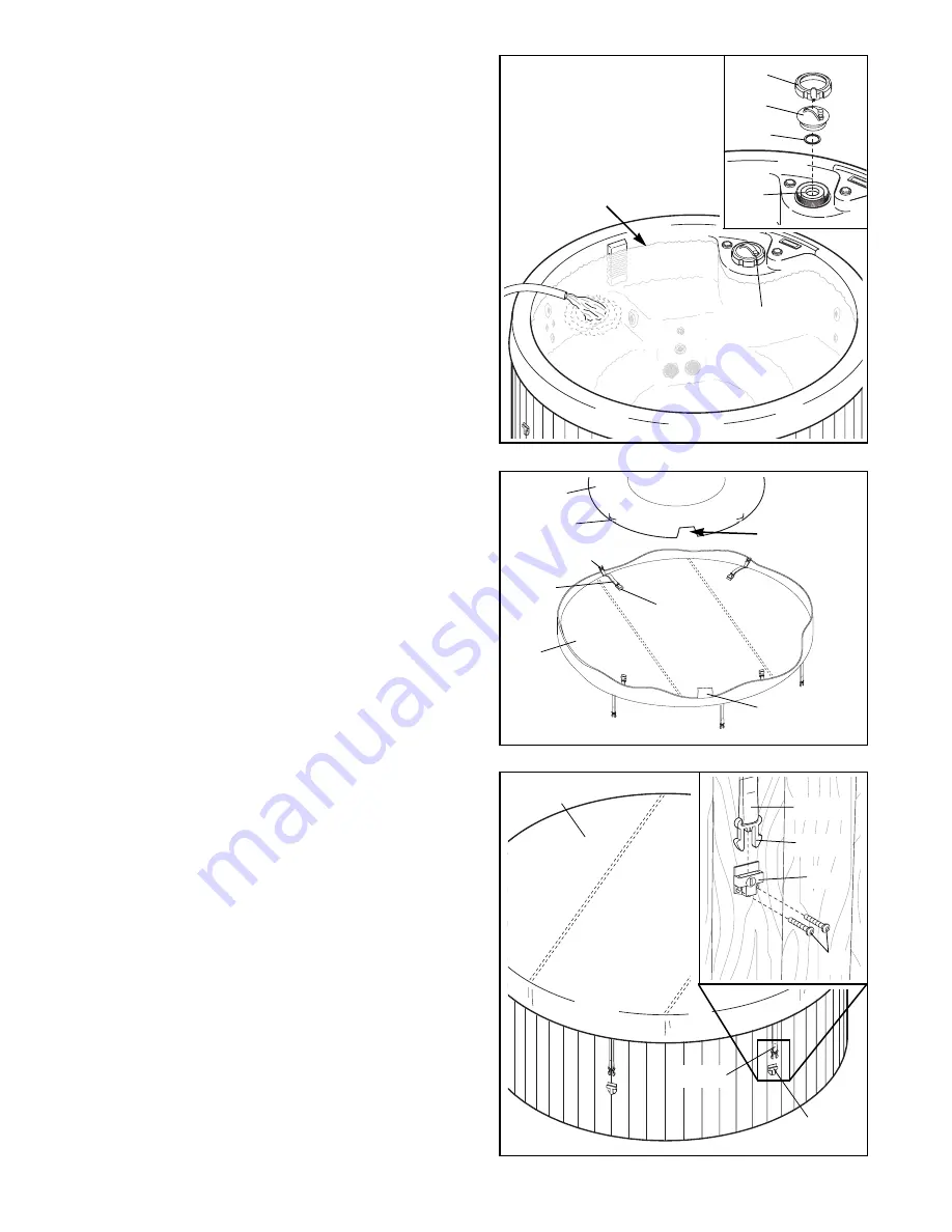
3. Refer to the inset drawing. Set a Filter Gasket (33)

on top of the Filter (16). Next, press the Filter Cover
(8) into the spa until it is fully seated. Then, tighten
the Locking Ring (19) onto the spa. 

Remove the two warning decals (not shown) from
the spa shell. Using a damp cloth, wipe the spa shell
clean. 

Before filling the spa, make sure that it is

in the desired position and that there is room to
easily service the spa. Once the spa is filled, it
will have to be drained before it can be moved.

Turn the Air Vent (29) counterclockwise to open
it. 

Using a garden hose or other clean water source,

begin filling spa. 

Do not use soft water.

The spa

may be filled with cold water; however, if warm or
hot water is used, the spa will be ready for use
sooner. Fill the spa until the water is at the level
shown at the right. 

Do not overfill the spa.

Turn the Air Vent (29) clockwise to close it.

4. Attach the nozzle of the included air pump to the

valves on the Inflatable Cover (4). Fill the Inflatable
Cover with air.

Do not overfill the Inflatable Cover.

Slide one of the straps on the inside of the Spa
Cover (11) through one of the loops on the Inflatable
Cover (4). Attach the latch on the strap to the buckle
on the other end of the strap. 

Make sure that the

cutout in the Inflatable Cover is lined up with the
warning label on the Spa Cover. 

Attach the other

three straps on the inside of the Spa Cover through
the loops on the Inflatable Cover in the same way.
Place the Spa Cover over the spa and line up the
cutout in the Inflatable Cover with the Console (not
shown).

5. Pull down one of the straps on the Spa Cover (11)

and hold the Buckle (30) against one of the wood
panels on the spa. (Note: To position the Buckle cor-
rectly, have a second person hold the strap on the
opposite side of the Spa Cover tight.) 

The Spa

Cover must be tight. Do not place the Buckle
over the grooves between the wood panels.

Refer

to the inset drawing. Remove the latch from the
Buckle (30). Attach the Buckle to the wood panel with
two #4 x 3/4Ó Screws (31). 

Note: It may be helpful

to use a drill with a 1/16Ó bit to make starter holes
in the wood panel. It may also be helpful to apply
a little soap or wax to the screw threads.

Attach the other five Buckles (30) to the wood panels
in the same way.

Remove the Spa Cover (11) and the Inflatable Cover
(not shown) from the spa.

3

4

Fill to Here

29

Loop

Buckle

Strap

Warning

Label

Cutout

Latch

4

11

5

11

30

Strap

Strap

Latch

30

31

19

8

33

16

Summary of Contents for IMHS45590

Page 1: ...our customer hot line will provide immediate assis tance free of charge to you CUSTOMER HOT LINE 1 877 897 7493 Mon Fri 6 a m 6 p m MST Model No IMHS45590 Serial No The serial number is found on a pl...

Page 2: ...6 Part List 18 Exploded Drawing 19 Ordering Replacement Parts Back Cover Limited Warranty Back Cover The warning sign shown below must be posted on a wall or fence where it will be visible to all user...

Page 3: ...se high temperatures can cause significant damage such as blistering of the shell surface and warping of the spa shell Any damage caused by sun exposure is not covered under the warranty 9 Do not brin...

Page 4: ...over when the spa is not in use 29 WARNING To reduce the risk of injury The water temperature should never exceed 104 F Temperatures between 100 F and 104 F are considered to be safe for healthy adult...

Page 5: ...e included warning sign must be posted where all users of the hydrotherapy spa can see and read it See POSTING THE WARNING SIGN on page 2 40 The causes symptoms and effects of hyper thermia may be des...

Page 6: ...your best For your benefit read this manual carefully before using the RENEW 455 If you have additional ques tions please call our Customer Service Department toll free at 1 877 897 7493 Monday throu...

Page 7: ...he spa provided you leave access to the motor for ser vice 9 Be sure to note any other considerations such as aesthetics or privacy concerns that may affect the safety or enjoyment of using the hydrot...

Page 8: ...drawings Read each assembly step before you begin Tighten all parts as you assemble them unless instructed to do otherwise ASSEMBLY REQUIRES THE FOLLOWING TOOLS not included One 1 phillips screwdriver...

Page 9: ...s on the Inflatable Cover 4 Attach the latch on the strap to the buckle on the other end of the strap Make sure that the cutout in the Inflatable Cover is lined up with the warning label on the Spa Co...

Page 10: ...ges of QUICK pHix It DOWN and QUICK pHix It UP However the directions on the bottle of Non chlorine Shox and Bromine Base are correct Always keep the chemi cals away from children and pets The first t...

Page 11: ...r operate the spa without the suction covers in place G The air control determines the amount of air flowing through the spa jets during operation see USING THE CONTROLS on page 12 H The filter can be...

Page 12: ...plugged in or if the buttons on the console have not been pressed for longer than twenty minutes the automatic mode will begin filtering or heating the water as needed Note To keep the filter and heat...

Page 13: ...ays be clean and dry before being moved or stored MAINTAINING THE SPA COVER The spa cover should be cleaned monthly To clean the spa cover use water and a non abrasive cleaner on the entire cover Rins...

Page 14: ...water you can either purchase additional test strips or purchase a pH test kit at a pool and spa supply store The pH read ing should be between 7 2 and 7 8 If the level is too low add a pH increaser...

Page 15: ...the spa 1 Drain the spa see DRAINING THE HYDROTHER APY SPA on the previous page and this page 2 Remove all remaining water from the spa shell Dry the spa shell with towels 3 Set the air control to the...

Page 16: ...e set temper ature b If you are using the hydrotherapy spa outdoors it may take longer for the water to heat See the chart below for the approximate heating time Air TemperatureHeating Time 70 F 16 to...

Page 17: ...ydrotherapy jets can be closed and opened by pushing and pulling the nozzles If no air flows through the hydrotherapy jets when the air control is turned counterclock wise simply pull the nozzles slig...

Page 18: ...ws 16 1 Filter 17 2 10 x 1 1 4 Screw 18 2 Suction Cover 19 1 Locking Ring 20 1 Pump Motor 21 1 Pump Motor Power Cord 22 1 Rubber Grommet 23 1 Light Cover 24 4 5 16 Lock Washer 25 1 Diverter Knob 26 3...

Page 19: ...19 18 17 11 5 4 22 35 25 33 19 15 8 16 7 2 7 9 10 26 18 31 30 34 23 3 10 33 32 29 26 10 24 5 12 21 14 6 13 28 27 20 6 12 13 1 Exploded Drawing Model No IMHS45590 R0300A...

Page 20: ...ng incidents any damage to the wood exterior resulting from improper maintenance or any damage to the wood or tile exterior attributable to freight mishandling damage resulting from improper winteriza...

Reviews: