background image

13

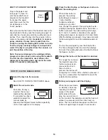
HOW TO TURN ON THE POWER

Plug in the power cord
(see page 11). Next, lo-
cate the reset/off circuit
breaker on the treadmill
frame near the power
cord. Make sure that the
circuit breaker is in the
“reset” position. 

Next, stand on the foot rails of the treadmill. Locate the
clip attached to the key (see the drawing on page 12),
and slide the clip securely onto the waistband of your
clothes. Then, insert the key into the console. After a
moment, the display will light. 

Important: In an emer-

gency situation, the key can be pulled from the
console, causing the walking belt to slow to a stop.
Test the clip by carefully taking a few steps back-
ward; if the key is not pulled from the console, ad-
just the position of the clip.

Note: To prevent damage to the walking platform,
always wear clean shoes while using the treadmill.
The first time the treadmill is used, observe the
alignment of the walking belt, and center the walk-
ing belt if necessary (see page 20).

HOW TO USE THE MANUAL MODE

Insert the key into the console.

See HOW TO TURN ON THE POWER above. 

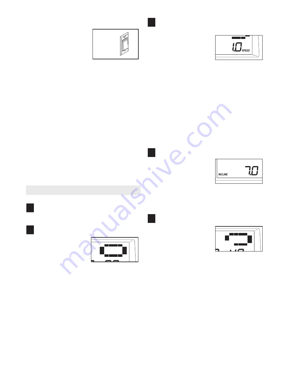
Select the manual mode.

Each time the key is
inserted, the manual
mode will be selected.
If a program has been
selected, reselect the
manual mode by
pressing the Program Select button repeatedly
until a track appears in the display.

Press the Start button or the Speed + button to
start the walking belt.

When either button is
pressed, the walking
belt will begin to move at
1 mph. Hold the
handrails and begin
walking. As you exer-
cise, change the speed of the walking belt as de-
sired by pressing the Speed buttons. Each time a
button is pressed, the speed setting will change
by 0.1 mph; if a button is held down, the speed
setting will change in increments of 0.5 mph. Note:
After the buttons are pressed, it may take a moment
for the walking belt to reach the selected speed set-
ting.

To stop the walking belt, press the Stop button.
The time will begin to flash in one of the displays.
To restart the walking belt, press the Start button or
the Speed + button.

Change the incline of the treadmill as desired.

To change the incline of
the treadmill, press the
Incline increase or de-
crease button. Each
time a button is
pressed, the incline will
change by 0.5%. Note: After a button is pressed, it
may take a moment for the treadmill to reach the
selected incline setting.  

Follow your progress with the display.

When the manual mode
is selected, a track rep-
resenting 1/4 mile will
appear in the upper
right corner of the dis-
play. As you walk or run
on the treadmill, the indicators around the track will
appear in succession until the entire track ap-
pears. The track will then disappear and the indi-
cators will again begin to appear in succession.

5

4

3

2

1

Reset

Position

Summary of Contents for IMTL39906.0

Page 1: ...r Decal QUESTIONS As a manufacturer we are com mitted to providing complete customer satisfaction If you have questions or if parts are damaged or missing PLEASE CONTACT OUR CUSTOMER SERVICE DEPARTMEN...

Page 2: ...BLY 6 OPERATION AND ADJUSTMENT 11 HOW TO FOLD AND MOVE THE TREADMILL 17 TROUBLESHOOTING 19 CONDITIONING GUIDELINES 21 PART LIST 23 EXPLODED DRAWING 24 ORDERING REPLACEMENT PARTS Back Cover LIMITED WAR...

Page 3: ...on the front cover of this manual and order part number 146148 or see your local electronics store 12 Failure to use a properly functioning surge suppressor could result in damage to the con trol syst...

Page 4: ...ative only 25 This treadmill is intended for in home use only Do not use this treadmill in a commer cial rental or institutional setting WARNING Before beginning this or any exercise program consult y...

Page 5: ...ou note the product model number and serial number before calling The model number of the treadmill is IMTL39906 0 The serial number can be found on a decal attached to the tread mill see the front co...

Page 6: ...do not use power tools for assembly 1 Make sure that the power cord is unplugged With the help of a second person carefully tip the tread mill onto its left side as shown Partially fold the Frame 86 s...

Page 7: ...t the Wheel should turn freely With the help of a second person carefully tip the tread mill onto its other side 66 13 69 64 3 4 Partially fold the Frame 86 so the treadmill is more sta ble Do not ful...

Page 8: ...rail 71 to the Left Upright 7 in the same way Note There is not a wire on the left side Remove the colored tie from the Upright Wire 42 Large Hole 72 95 42 37 37 95 71 90 7 7 5 Attach two Round Base P...

Page 9: ...he connector 72 47 9 47 10 Set the Console Base 47 on the Handrails 71 72 Attach the Console Base with four 3 4 Screws 2 Start all four Screws before tightening them do not over tighten the Screws See...

Page 10: ...ring are on the pin as shown Then in sert the pin into the Latch Housing 29 and tighten the knob back onto the pin Pin Collar Spring Knob 7 29 2 13 Large Hole 42 36 47 11 Cover the Upright Wire 42 wit...

Page 11: ...alfunc tion or break down grounding provides a path of least resistance for electric current to reduce the risk of elec tric shock This product is equipped with a cord having an equipment grounding co...

Page 12: ...y continuous exercise feedback You can even measure your heart rate using the built in handgrip pulse sensor In addition the console features four preset programs Each program automatically controls t...

Page 13: ...appears in the display Press the Start button or the Speed button to start the walking belt When either button is pressed the walking belt will begin to move at 1 mph Hold the handrails and begin walk...

Page 14: ...cts on the handgrip pulse sensor In addition make sure that your hands are clean To measure your heart rate stand on the foot rails and hold the metal contacts on the handrail avoid moving your hands...

Page 15: ...t tings will move one column to the left The speed setting for the second period will then be shown in the flashing Current Period column and the tread mill will automatically adjust to the speed and...

Page 16: ...if desired Important If a d appears in the dis play the console is in the demo mode This mode is intended to be used only when a treadmill is displayed in a store When the console is in the demo mode...

Page 17: ...frame until the latch catch is aligned with the latch pin Slowly release the latch knob make sure that the latch pin is resting securely against the latch catch To protect the floor or carpet from dam...

Page 18: ...he frame down until it is past the latch pin 2 Hold the metal frame firmly with both hands and lower it to the floor CAUTION To decrease the possibility of injury do not lower the frame by gripping on...

Page 19: ...ff during use SOLUTION a Check the circuit breaker located on the treadmill frame near the power cord see the drawing above If the circuit breaker has tripped wait for five minutes and then press the...

Page 20: ...t is off center or slips when walked on SOLUTION a If the walking belt is off center remove the key and UNPLUG THE POWER CORD If the walking belt has shifted to the left use the allen wrench to turn t...

Page 21: ...that requires large amounts of oxygen for prolonged periods of time This increases the demand on the heart to pump blood to the muscles and on the lungs to oxygenate the blood For aerobic exercise adj...

Page 22: ...les Stretch With one leg in front of the other reach forward and place your hands against a wall Keep your back leg straight and your back foot flat on the floor Bend your front leg lean forward and m...

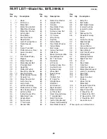
Page 23: ...her 53 1 Incline Motor Bolt Lower 54 3 Incline Pivot Bolt 55 1 Filter Wire 56 1 Motor Controller Wire 57 4 Round Base Pad 58 13 3 4 Tek Screw 59 1 Controller 60 1 Lift Frame 61 2 Extension Leg Pad 62...

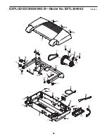
Page 24: ...83 97 32 96 86 32 73 52 73 83 82 92 40 92 89 87 68 100 15 94 112 11 85 84 84 58 30 31 25 67 67 49 25 25 25 25 25 25 25 25 25 9 9 44 74 44 84 85 41 41 52 80 2 2 23 23 67 67 112 24 EXPLODED DRAWING A Mo...

Page 25: ...55 1 22 22 22 3 6 8 103 20 28 28 20 56 81 58 58 79 92 77 26 59 58 58 77 77 26 77 77 10 58 12 19 13 13 60 73 13 12 91 4 41 4 6 25 EXPLODED DRAWING B Model No IMTL39906 0 R0806A...

Page 26: ...7 39 39 57 51 108 13 62 63 64 13 66 65 39 61 39 61 57 99 13 54 13 54 93 46 65 93 63 46 104 64 66 13 42 101 106 24 102 105 78 2 37 95 16 16 57 95 21 99 21 95 99 99 76 76 107 108 107 107 95 95 35 26 EXP...

Page 27: ...2 2 2 48 48 2 2 2 27 2 2 75 36 34 88 50 47 43 38 45 110 111 109 27 EXPLODED DRAWING D Model No IMTL39906 0 R0806A...

Page 28: ...r consequential damages arising out of or in con nection with the use or performance of the product or damages with respect to any economic loss loss of property loss of revenues or profits loss of en...

Reviews: