background image

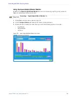
Selenio  BNP User Guide, Release 3.7.1

185

CHAPTER 7

Maintenance

This chapter describes how to use the 

BNP Element Manager

 to perform maintenance tasks. 

Applicable Platforms: 

The information in this chapter can be used with any BNP device. 

In This Chapter:

“Software Upgrade,” next.

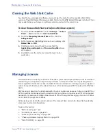
“Clearing the Web Start Cache” on page 190.

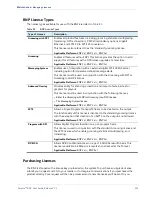
“Managing Licenses” on page 190.

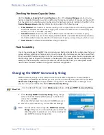
“Changing the SNMP Community String” on page 193.

“Configuring the Time Offset Table (TOT)” on page 194.

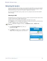
“Rebooting the System” on page 196.

“System Shutdown” on page 197.

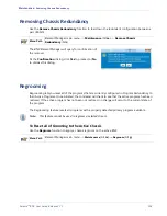
“Removing Chassis Redundancy” on page 198.

“Regrooming” on page 198.

“Force Re-allocation of TS” on page 199.

Software Upgrade

To upgrade to the latest BNP software, download the software from an FTP server and use the BNP 

Element Manager

 upgrade feature to perform the upgrade. You will receive the specific information 

about the upgrade software when you purchase an upgrade, or when you are notified that an upgrade 

is available. 

In most cases, you can simply upgrade from your currently running release to the most recent, 

regardless of the sequence of releases in between (see “Upgrade Sequence” on page 186). However, 

systems running BNP software previous to 3.5.0 must first upgrade to 3.5.0 prior to attempting an 

upgrade to the currently available release. 

Note:

Always refer to the Release Notes for supported upgrade paths. 

Use this section to find out how to upgrade a standalone BNP, or the active and standby BNPs in a 

redundant configuration, as described in the following topics:

“Upgrade Sequence,” next.

“Upgrading Software in a Single Chassis Environment” on page 186. 

“Upgrading Software in a Redundant Chassis Environment” on page 188

Note:

Please contact Imagine Communications Customer Support for assistance in performing a 

software downgrade process.

Summary of Contents for Selenio BNP 2xr

Page 1: ...User Guide SelenioTM Broadcast Network Processor BNP Release 3 7 1 18 December 2015 Revision A...

Page 2: ...s components or documentation as progress may warrant to improve the performance of the product Trademarks SelenioTM and TelurioTM are trademarks of Imagine Communications Microsoft and Windows are re...

Page 3: ...control to MPEG 2 aggressive rate control Add long delay for H 264 DPI to output TS 250 0146 01 rev A 3 5 0 4 30 12 Quick Keys shortcuts Updated safety information Updates for localization 250 0136 0...

Page 4: ...synchronization feature Output TS modification enhancements DVB CA enhancements Added ES level grooming 250 0052 01 rev B 3 0 1 05 07 2010 Added Operator Advanced Messaging and Logo Overlay schedulin...

Page 5: ...Multiplexing 15 DPI Based Ad Splicing 15 Messaging System Applications 16 DVB Conditional Access DVB CA Encryption 17 BNP Deployment Architecture 17 Redundancy 20 Source Specific Muliticast SSM Redund...

Page 6: ...ion 52 Local User Authentication Configuration 53 Managing Local User Accounts 54 User Authentication Server Configuration 57 Messaging System Configuration 60 About Messaging Zones 60 EAS Messaging Z...

Page 7: ...163 Dummy PIDs 164 Adding an Unreferenced PID as an Elementary Stream 167 Elementary Stream Ghost PID Management 170 Unreferenced PID Pass Through 171 Unreferenced PID Mapping 172 Referenced PID Mapp...

Page 8: ...to Output DVB TS 214 Creating Input PSI SI Table Grooming 217 Grooming the Ghost Program to Output DVB TS 218 Configuring DVB CA Global Parameters 219 Configuring DVB CA External and Internal EIS Mod...

Page 9: ...f Contents Naming Viewing Deleting and Editing NIT Configuration Files 257 Naming a Configuration File 257 Viewing a Configuration File 259 Deleting a Configuration File 260 Editing a Configuration Fi...

Page 10: ...BNP 3xr Receiving input through its Gigabit Ethernet or ASI interfaces the BNP can statistically multiplex while performing grooming and digital ad and overlay insertion The BNP can receive both stand...

Page 11: ...pter 9 DVB Conditional Access describes how to set up DVP CA system using the BNP Chapter 10 ETV Binary Interchange Format provides an overview of EBIF and typical use cases for configuration Chapter...

Page 12: ...ing This shows that failure to take the necessary precautions or to follow guidelines could cause harm to equipment and personnel Navigation tip follow the path alongside the pointer to navigate to a...

Page 13: ...oming and digital program insertion DPI transrating video streams with impressively high video quality Multiple levels of redundancy support including service level and 1 1 chassis level redundancy Su...

Page 14: ...igure and pass through both long and short names for ATSC TS output programs EBIF FAT ASI transport services multiple program groups over a single TS ASI interface H 264 grooming and multiplexing in a...

Page 15: ...enabling selection of the desired level of transrating DPI Based Ad Splicing The BNP can concurrently groom and seamlessly splice both SD and HD program streams encoded in either MPEG 2 or H 264 forma...

Page 16: ...leading EAS management vendors for a completely customizable deployment A BNP in an SCTE 18 digital EAS application is shown in Figure 5 Figure 5 BNP in SCTE 18 Digital EAS Application RGB Broadcast...

Page 17: ...elated PSI SI generation and insertion SimulCrypt EIS Lite GUI configuration and management RGB s SimulCrypt engine interfaces with the following external devices Event Information Scheduler EIS Entit...

Page 18: ...ciency offered with this transport while still providing support for operators with legacy ASI networks This flexibility enables operators with ASI networks to continue with their existing infrastruct...

Page 19: ...network for a centralized system architecture using ASI interfaces GigE interfaces could also be used for both input and output in a co located headend application Figure 9 Example of Co Located ASI...

Page 20: ...ce configured for that input TS All the streams coming from various sources must be identical PIDs program numbers number of programs etc Therefore it does not matter which source specific multicast t...

Page 21: ...e mirrored GigE port simultaneously as a fully operational redundant output GigE port Regardless of mirroring all active GigE ports must have unique IP addresses assigned To set GigE port level redund...

Page 22: ...y using Heartbeat and Virtual IP Failover Mechanism GigE Switch Router 10 100BaseT Switch Router Media IP Transport Network Control IP Network GigE8 Heartbeats 10 100BaseT Heartbeats Port 10 100BaseT...

Page 23: ...ge 31 Chassis Tab on page 31 BNP Version Information on page 33 Quick Keys on page 35 BNP Element Manager Overview The BNP Element Manager is a Java based GUI available using a standard web browser wh...

Page 24: ...stalled on the BNP at the factory and is presented as a home page Figure 11 following entry of a BNP s network address from a web browser In addition to providing access to the BNP Element Manger seve...

Page 25: ...field Table 4 and Table 21 on page 50 At the Password field type the password string Note that passwords are case sensitive Table 4 BNP Element Manager User Accounts User Password Privileges Administr...

Page 26: ...navigate to the various functions by selecting options from the tabs and menus and menu items are associated with keyboard mnemonics for quck access Figure 12 Figure 12 Hierarchy of BNP Element Manag...

Page 27: ...13 BNP Element Manager GUI Components BNP Element Manager Menu Tab screen Connectivity Status standby BNP IP address and status of active BNP Alarm Notification Tab Banks System Name BNP Model IP Addr...

Page 28: ...rm a BNP shutdown remove BNP redundancy or regroom DVB CA 3xr Perform global DVB CA configuration Help All Access the About screen in which to view current release information about the BNP in use Tab...

Page 29: ...ny other part of the BNP displays system information about the BNP See also Chassis Tab on page 31 Maintenance Alt m Access BNP maintenance functions with the following options Upgrade Software Softwa...

Page 30: ...t critical event reported by the BNP is displayed as a text string and color code Table 8 in the middle section of the status bar Table 8 BNP Element Manager System Status Color Meaning Green Informat...

Page 31: ...t ASI port directions as either Input or Output See also ASI Port Configuration on page 47 User Authentication Set parameters for BNP Element Manager user accounts See also User Authentication Configu...

Page 32: ...of the FPGA chip is displayed enabling easy determination that the FPGA die temperature is within acceptable limits If the value of any component inside the chassis exceeds 100 an alarm is generated...

Page 33: ...ber displayed alongside the Chassis Software Version field Figure 16 Figure 16 Viewing Software Version Information from Chassis Page Menu Path From the Help menu select About to present the About scr...

Page 34: ...SelenioTM BNP User Guide Release 3 7 1 34 BNP Element Manager Basics BNP Version Information Figure 17 Viewing Software Version Information from BNP Element Manager About screen...

Page 35: ...ions from the BNP Element Manager main menu Alt v Alt r Refresh the current view of the BNP Element Manager screen Alt v Alt e Expand the current view in the Grooming Mapping tab page to reveal all cu...

Page 36: ...r entry redundancy configuration and full configurability of ASI and Gigabit Ethernet ports This chapter describes how to configure the BNP using the BNP Element Manager You can also use the BNP Eleme...

Page 37: ...to managing active and standby BNPs Figure 18 Global tab screen 1 At the Global tab screen use guidelines from the following tables to set parameters for the BNP system Table 12 System Time Source Gl...

Page 38: ...able 13 Time Zone Name Log Address Global Configuration Field Description Values Time Zone If Internal is selected choose the time zone from the pull down list that coincides with the location of the...

Page 39: ...r ETH 2 Applicable Platform BNP 3xr Optional Enter the IP address of the gateway default router that the ETH 2 DVB CA port should use This address must be the same on both the active and standby chass...

Page 40: ...exist Note If you disable EAS CAP after having it enabled any existing messaging zones will be retained but the messages will be truncated to the first 400 characters Note Changing this setting requir...

Page 41: ...Check this to insert black frames before transitioning back to the network when AD underflows This will allow a smooth transition between the AD that under flowed and the network DPI Splicing Accurate...

Page 42: ...n redundant BNP configurations should be conducted during a maintenance window Use steps in this section to perform the following forced synchronizations on the BNP Forcing Synchronization of the BNP...

Page 43: ...figuration Ethernet Control Port 1 At the Ethernet Control Port tab screen enter and or type Ethernet control port values Use the following guidelines for IP addressing of these ports The IP address f...

Page 44: ...Note If you use DHCP rather than a static IP address for your Ethernet control port configuration you will need the assistance of Imagine Communications customer support Contact them before you choos...

Page 45: ...Address Read only the MAC address of the port IP Address The IP address for the interface if no IP address is used leave the field empty Note that the Element Manager allows the IP address of the Gig...

Page 46: ...e IP address Configuring GigE Port Mirroring Use the GigE Ports tab screen Figure 21 to define port pairs for mirroring Menu Path BNP Element Manager Configuration tab GigE Ports tab screen Figure 21...

Page 47: ...to Set button is displayed The mirrored to GigE port is no longer listed in the Mirrored to column The Set button at the originating port is replaced by the Set button There is no need to click Apply...

Page 48: ...is field to change the setting Note To enable display of an ASI port on the Inputs panel of the Grooming Mapping window the port direction must be Input To enable display of an ASI port on the Outputs...

Page 49: ...ion authorization and accounting AAA server that supports RADIUS or TACACS The AAA server handles requests for access to system resources to be configured allowing maintenance of user profiles to be p...

Page 50: ...bled in Element Manager Use local authentication Localauthentication success Authentication failed Login rejected Log error Login failure Go to next server Yes No No Yes No No Yes Go to C C Go to A No...

Page 51: ...yes admin UP admin no na na fail na failed DOWN admin yes no na fail yes faileda a network down or server not stated user not present in local db TACACS UP admin yes na na pass no admin DOWN admin yes...

Page 52: ...er fields 2 Use guidelines in Table 23 for entries in this screen 3 Click Apply Configuration to save and load the settings Table 23 User Authentication Global Fields Field Description Enable Enable c...

Page 53: ...ed protocol to use in selecting a server Valid options are Radius Try all RADIUS servers before trying TACACS servers TACACS Try all TACACS servers before trying RADIUS servers Default Radius Remote O...

Page 54: ...nfiguration are allowed Default password is User Operator Read and write access are allowed for all configuration operations except changing passwords Default password is Operator Administrator Full a...

Page 55: ...privilege level as either Administrator Operator or User for this user account from the drop down menu For more information about privilege levels see Table 21 User Privileges and Operations on page...

Page 56: ...user accounts Deleting a Local User Account Use the Delete button on the Local tab screen to instruct deletion of a specified user account Menu Path BNP Element Manager Configuration tab User Authenti...

Page 57: ...t AAA Server Order in the next section About AAA Server Order The order in which the system attempts to connect to an AAA server is based on the following criteria The preferred authentication protoco...

Page 58: ...ption is selected from the AAA Global Configuration menu See Global User Authentication Configuration on page 52 for more information Figure 31 Add or Edit AAA Server Adding an AAA Editing an AAA 1 At...

Page 59: ...server order is the order in which the AAA servers were added to the list This field is read only Change Order To The new server order to use Separate each number with one space The same number of ser...

Page 60: ...one or more programs as a digital logo overlay To configure these features you must create specific Messaging or Logo Overlay zones under the Messaging System tab which are then associated to desired...

Page 61: ...received EAS event code EAN EAT NIC RMT RWT NPT It processes the event based on the alert remaining time and priority of the received EAS message Accessing Messaging Zones Use the Message Zones tab s...

Page 62: ...r Messaging Loaded Operator message is loaded on the BNP and is ready to start the operator message Operator Messaging Text On Operator Alert Message is loaded on the BNP and crawl text is displaying...

Page 63: ...ed audio sources from the EAS system 15 highest priority The BNP offers user configuration to allow adherence to the SCTE 18 specification to override both video and audio on a detailed channel with t...

Page 64: ...Messaging on page 65 Table 35 EAS Zone Control Configuration on page 65 Table 36 EAS Crawl Configuration on page 66 Table 37 EAS Zone Status on page 66 Table 38 EAS Alert Text on page 66 2 Click Appl...

Page 65: ...35 Not required for ASI ports Program Number Input the program number on which the program information is received for EAS messaging Audio Override Delay In Secs Specifies the delay of audio splicing...

Page 66: ...7 EAS Zone Status Field Description Start Time Read only Displays the day date and time that the crawl has or will begin Applies to both external SCTE 18 EAS server and Operator Alert messages Remaini...

Page 67: ...ries are provided in the following topics Table 33 Zone Index for EAS Messaging on page 64 Table 34 EAS Video Configuration for EAS Messaging on page 65 Table 35 EAS Zone Control Configuration on page...

Page 68: ...tor to generate a text crawl of up to 400 characters in length directly from the BNP Element Manager or to specify a text or graphic file as an overlay Both Operator and Advanced zones can be associat...

Page 69: ...r Messaging Configuration Schedule on page 70 Table 43 Operator Messaging Configuration Zone Status on page 71 2 Click Apply to save changes and create the messaging zone Table 39 Operator Messaging C...

Page 70: ...r one cycle minimum Message will play for the duration that is longest Specified value of seconds OR one cycle Continuous Continuously plays message until the Stop Crawl button is clicked Frequency Ch...

Page 71: ...that the next round of messaging will begin Overlay Image Read only field Applicable to Advanced Messaging tab Displays the status of the graphic and or text overlay Possible values are Complete An i...

Page 72: ...d Messaging Zone screen for a specified zone to change parameters for the messaging zone Menu Path Messaging System Messaging Zones double click the messaging zone or right click the zone to be modifi...

Page 73: ...n Note An Advanced Overlay license must be purchased in order to view or configure an Advanced Messaging Zone For more information on Advanced Overlay licensing see Managing Licenses on page 190 Figur...

Page 74: ...uration of the alert the time remaining is displayed here Event Duration Read only field Displays how long the event is to take place Current Status This field is read only and will display one of the...

Page 75: ...r load time and bandwidth on the BNP You may type in any value from 0 to 100 or choose a value from the drop down box as follows 0 opaque 25 50 75 and 100 NOTE This box will not be displayed unless Tr...

Page 76: ...he message for the specified number of seconds with a 5 second or one cycle minimum Message will play for the duration that is longest Specified value of seconds OR one cycle Continuous Continuously p...

Page 77: ...will enable real time polling of the Zone Status fields as well as any Operator defined text crawls When the Enable Status Update button is clicked and real time polling enabled the button will change...

Page 78: ...P The system will query for confirmation of the deletion as follows Where no output transport streams are associated with the selected zone you will be asked to confirm deletion and the zone will be d...

Page 79: ...31 on page 61 for a description of status messages Make any changes to the desired subtab Operator or Advanced Click Apply to load the new message to the BNP s memory If the Enable Status Update butto...

Page 80: ...s a view in which transparency is enabled Figure 41 Alpha Channel Transparency Examples Alpha channel transparency has been configured in the PNG file but not enabled on the BNP Alpha channel transpar...

Page 81: ...BNP and is ready to start overlay Logo On Logo is loaded on the BNP and is currently displaying in the zone Scheduled Logo has been loaded and scheduled but currently is not being displayed Recommend...

Page 82: ...e placed within the bounds of an SD screen at 720 x 480i resolution Figure 43 Logo Overlay Positioning 0 960 540 X Y 0 0 Top Left Right Left Bottom Top Bottom Right 540 0 960 Logo Logo Logo Logo 0 360...

Page 83: ...ion Parameter and button descriptions are provided in the following tables Table 50 Zone Index and Name Zone Overlay on page 84 Table 51 Logo Configuration Zone Overlay on page 84 Table 52 Zone Status...

Page 84: ...s right most edge would start 32 pixels from the right quadrant of either the top or bottom quadrant whichever is selected Y Position 0 to 540 Multiple of 16 pixels Enter the pixel number in multiple...

Page 85: ...y field Displays the time that the next round of messaging will begin Table 53 Logo Import Zone Overlay Field Description Logo Image Displays the location and name of the imported graphic that has bee...

Page 86: ...ow to display a popup window seen in Figure 37 Advanced Messaging Schedule Window on page 71 to set start Schedule Stop button Forever If message is set to play once see Frequency above this is the de...

Page 87: ...rlay Zone Note If a Logo Overlay is currently On click the Enable Status Update button to see real time status updates of the zone stop the overlay first before modifying desired parameters Figure 45...

Page 88: ...e EAS Operator and Advanced or Logo Overlay can be enabled or associated to a particular program at the same time If all associated zones have been activated the priority of message playout is as foll...

Page 89: ...vent starts Once a program has been associated with a Messaging Service zone the program can then be enabled or disabled for the specified zone either from the Grooming Mapping screen see Managing Out...

Page 90: ...for Messaging At the Zone Program List screen use either the popup menu or screen buttons to enable or disable a specific program for messaging uTo use the popup menu highlight then right click on a p...

Page 91: ...onfigured and enabled for messaging Figure 47 Messaging Zone Icons Messaging configured enabled program Messaging configured disabled program Refreshing a Program List Click the Refresh button from th...

Page 92: ...you can configure from one to eight trap addresses each of which will issue event notifications to the network management status You can change this SNMP information at any time To Configure SNMP for...

Page 93: ...perational Upon detection of no heartbeat the standby system takes over operations until the previously active system is ready to resume operations Heartbeats are detected primarily over the IP networ...

Page 94: ...s missing for over 2 seconds the 1 1 chassis failover is used instead of standby program failover Note For hot standby 1 1 chassis redundancy configured with virtual IP failover unicast inputs cannot...

Page 95: ...current role of this chassis as either Primary or Standby Redundancy Switch button Toggle the Primary and Standby BNPs in a redundant configuration IP Address for 10 100 Enter the IP address of the 1...

Page 96: ...ge 25 2 If you have not already done so go to the Configuration Ethernet Control Port tab screen and change the IP Configuration IP Address Subnet Mask and Gateway fields for Ethernet Port 1 and Ether...

Page 97: ...Step 1 of 2 Configure the Standby BNP Chassis on page 96 1 Log in to Element Manager of the active chassis as described in Log in and Access the BNP Element Manager on page 25 2 From the BNP Element M...

Page 98: ...r password then click OK The system now queries for confirmation to reboot this BNP 5 At the The Reboot confirmation window click Yes 6 Allow the standby BNP to reboot and return to its available back...

Page 99: ...Virtual IP Address none blank IP Address for GigE port Port IP of GigE 8 of the standby BNP This configuration will ensure that the active and standby BNPs may continue to listen for heartbeats if the...

Page 100: ...tab screen and disable uncheck Auto Negotiation for GigE 8 Figure 51 Figure 51 Active BNP Disable Auto Negotiation Uncheck disable auto negotiation for GigE 8 3 Go to the Configuration Global tab scre...

Page 101: ...From the BNP Element Manager of the standby chassis go to Configuration GigE Ports tab screen and disable uncheck Auto Negotiation for GigE 8 Figure 53 Figure 53 Standby BNP Disable Auto Negotiation...

Page 102: ...1 102 System Redundancy Configuring GigE Ports for Heartbeat Detection Virtual IP Address Configuration for GigE 8 Make sure this field is blank Figure 54 Standby BNP Set Chassis Redundancy ENTER INF...

Page 103: ...s on tasks performed with the Grooming function to map transport streams and programs and to monitor bitrates Applicable Platforms The information in this chapter can be used with any BNP device In Th...

Page 104: ...n individual programs or full transport streams Drag and Drop Grooming on page 140 Set program schedule Scheduling Grooming One time event on page 151 Menu Path BNP Element Manager Grooming tab Mappin...

Page 105: ...Name Show Port Usage TS Modify Transport Stream Refresh Transport Stream Tables Recreate Input Transport Stream Create Ghost Program Bitrate Monitor Ghost Program Modify Ghost Program Delete Ghost Pr...

Page 106: ...nding and collapsing affect only the display This function does not change the underlying grooming To expand the view of an individual entity click on the symbol and the content will be revealed To co...

Page 107: ...put or output program Audio MPEG1 MPEG2 AC 3 0x06 AC 3 0x81 AAC 0x0f HE AAC 0x11 E AC 3 Represents the presence of an audio elementary stream on an input or output programs Available audio options are...

Page 108: ...w highlighted in the Inputs panel The highlighted row is grooming source for the selected program Figure 58 Viewing program level input source Data 5 6 Teletext 6 Sub Title 7 191 192 193 255 Represent...

Page 109: ...ch is the grooming source for the selected program Figure 59 Viewing ES level input source Highlighted source Creating Input Transport Streams The information required to create a transport stream TS...

Page 110: ...ource Specific Multicast SSM mode If checked you can configure up to four source IP addresses SSM Redundancy can only be checked if Multicast is also checked IP Address The unicast or multicast IP add...

Page 111: ...s and to place the new TS at the Inputs panel of the Mapping screen see example in Figure 62 Table 61 Selecting Multiple IP and UDP Field Description Start IP Address A read only field indicating the...

Page 112: ...Transport Stream Options next ASI Port Transport Stream Options on page 112 GigE Port Transport Stream Options Use the popup menu from an input GigE port to view and select operations that can be per...

Page 113: ...the transport stream with no associated grooming Create Ghost Program Used for created programs with unreferenced PIDs See Adding an Unreferenced PID as an Elementary Stream on page 167 for details B...

Page 114: ...ue TS ID Allows you to assign a unique numeric ID to this transport stream When this option is checked the TS ID value placed in this field will be reserved as unique for the entire chassis When this...

Page 115: ...configuration of Messaging System zones for specific programs in this transport stream See Messaging System Configuration on page 60 for information on configuring Messaging Zones MPEG 2 Aggressive Ra...

Page 116: ...D value placed in this field will be reserved as unique for the entire chassis When this option is unchecked a TS ID value may still be entered however the value may be the same as another TS ID as lo...

Page 117: ...that classifies network traffic and provides QoS The BNP allows you to configure a DSCP value for IP packets generated for any type of GigE output transport stream See also Using DSCP on page 118 Def...

Page 118: ...s only to output transport streams on GigE ports any DSCP on input streams is not carried forward into output streams You can modify a DSCP value at any time following creating of the output transport...

Page 119: ...ut Transport Stream dialog Figure 68 and Table 65 Menu Path From the Outputs panel of the Grooming tab Mapping tab screen right click on an ASI port and select Create Transport Stream from the popup m...

Page 120: ...am dialog TS Type field select ATSC The dialog now provides entry fields for PSIP tables that can be applied to the selected GigE port Figure 69 Create Output Transport Stream GigE ATSC Select ATSC to...

Page 121: ...ble this option CVCT TVCT Interval ms Specifies the interval in milliseconds at which CVCT TVCT tables are generated If the Generate TVCT option has been enabled this field sets the interval for TVCT...

Page 122: ...from Table 63 to provide port information in the remaining fields 2 Click OK to save your settings and to place the new SCTE transport stream in the Outputs panel of the Grooming Mapping tab screen b...

Page 123: ...OK to save your settings and to place the new SCTE transport stream in the Outputs panel of the Grooming Mapping tab screen beneath the selected GigE port Creating DVB Output Transport Streams Use the...

Page 124: ...portion Use guidelines from Table 66 to provide the DVB information 2 Click OK to save the settings and to put the new TS at the Outputs panel of the Mapping screen beneath the selected GigE port Cre...

Page 125: ...iguration Parameters Field Description Network ID Input the Network ID of the current transport stream Modulation Mode Use the pull down menu to select the modulation mode used for the TS Choice betwe...

Page 126: ...work Information Table NIT dialog to perform the following operations Adding a NIT next Editing a NIT on page 127 Deleting a NIT on page 128 Menu Path From the main BNP Element Manager menu select Mai...

Page 127: ...dit Network Information Table NIT screen Figure 75 to modify a NIT You can also use this screen to access the XML version of the NIT file or to import a NIT file from another BNP Menu Path From the ma...

Page 128: ...ormation Table NIT dialog click Delete Creating a FAT ASI Port Output Transport Stream Use the Create Output Transport Stream FAT ASI dialog Figure 76 and Table 67 to set parameters for up to four FAT...

Page 129: ...ced in this field will be reserved as unique for the entire chassis When this option is unchecked a TS ID value may still be entered however the value may be the same as another TS ID as long as that...

Page 130: ...zones for specific programs in this transport stream See Messaging System Configuration on page 60 for information on configuring Messaging Zones Number of Group The number of groups you want to assi...

Page 131: ...s Manually Use the Create Output Program dialog to set parameters for an output program Fields displayed in the ETV Configuration portion of this dialog are the result or PIDs priority setting as eith...

Page 132: ...is entry in applicable screens is dependent on the current setting as either hexadecimal or decimal for Configuration Global PID Display Major Channel Number Operator defined channel number for terres...

Page 133: ...e output program will be dropped during the ad Play during ad only provides the ability to select the input EBIF ES source that will be playing only during the ad time if an EBIF ES source is not avai...

Page 134: ...r in the drop down menu Table 69 describes the fields available in the Program Messaging System Setting window Table 69 Messaging System Setting window Field Description EAS Zone Select an EAS zone fr...

Page 135: ...ut Transport Stream dialog to change the name of an input transport stream Other parameters cannot be modified Menu Path From the inputs side of the Grooming Mapping tab screen right click on a TS ass...

Page 136: ...Modify Output Transport Stream dialog enter parameters to editable fields Note that certain parameters are common to all transport stream types Table 64 on page 116 additional parameters can be modif...

Page 137: ...y Output TS ASI port 1 At the Modify Output Transport Stream dialog enter parameters to editable fields Note that certain parameters are common to all transport stream types Table 63 on page 114 addit...

Page 138: ...an existing input program name Menu Path From the inputs panel of the Grooming Mapping tab screen right click on a program and select Modify Program Name from the popup menu Figure 83 Program Pop Up m...

Page 139: ...odify Output program GigE or ASI port 1 At the Modify Output Program dialog enter parameters to editable fields see also Table 68 Create Output Program Configuration Parameters on page 132 for descrip...

Page 140: ...s Grooming Behavior Transport Stream to Transport Stream Deletes all current programs and replaces them with the dragged Transport Stream Transport Stream to GigE Port The entire Transport Stream is c...

Page 141: ...ram and drop it onto a specific output transport stream to present the Configure Program Mapping Grooming tab screen Figure 86 Figure 86 Drag input program to output TS Drag selected program from the...

Page 142: ...the program as described in Program Messaging System Setting on page 134 Note As of BNP Release 3 7 1 the Element Manager allows you to groom an input Ghost program to an output TS 1 At the Grooming...

Page 143: ...Conversion TS ID Read only Specifies the input Transport Stream ID used for the input program Program Number Read only Specifies the program number for the input program Program Name Read only Specif...

Page 144: ...the ETV PIDs Priority is set to Network the following three options will appear in a drop down box Play through ad any EBIF ES data that is part of the output program will continue to be played during...

Page 145: ...up to 32 characters can be entered to define the long name to be passed through PMT PID Select this option to activate the PMT ID box into which you can then enter the PMT ID or the ID of the program...

Page 146: ...om 8 to 8 0 off Bypass Transrater not for use when grooming a DPI enabled program Handle as Data not for use when grooming a DPI enabled program No Rate shaping See also Table 79 Quality of Service Le...

Page 147: ...an be displayed YES Output video ES uses the same bandwidth as input video ES Can not use more than the bandwidth of output TS Handle As Data Video ES is not processed through the transrater Video can...

Page 148: ...Stream Mapping screen is now presented Note For information about various data stream types and their icons see Table 59 on page 107 Figure 88 ES to Program Drag and Drop Drag selected generic data fr...

Page 149: ...number of the output program to which the ES will be groomed Program Name Displays the destination program name of the output program name to which the ES will be groomed PMT PID Displays the Program...

Page 150: ...stream may only be groomed on top of an existing ES level groomed elementary stream not a program level groomed stream and the Stream Types of the input ES and the output ES must match Figure 89 ES to...

Page 151: ...ES level grooming The presence of ES level grooming is indicated by a black asterisk next to the relevant ES in the Component PIDs section of the Current Program Mapping and Schedule window 3 Click Re...

Page 152: ...click OK To set a stop time set the time and date for grooming to stop and click OK 4 Click OK to apply the mapping to the program Program Redundancy The BNP supports program level redundancy on all...

Page 153: ...or Missing PAT PMT detection Manual recovery operation is based on the user selecting when a single program or all programs should be recovered to their respective primary programs Configuring Program...

Page 154: ...oTM BNP User Guide Release 3 7 1 154 Grooming and PSIP Grooming Mapping Figure 91 Configure Program Mapping Program Redundancy on GigE Port Figure 92 Configure Program Mapping Program Redundancy on AS...

Page 155: ...and right click 3 From the pop up menu select Switch to Backup The Switch to Backup option is available when the selected program is already in the Manual Recovery to Primary Program operation mode Th...

Page 156: ...the Grooming Mapping tab screen right click on a program and select Manage Elementary Streams from the pop up menu Note An ES Type Stream Type PID number Dummy value and Preconfigured for PMT value c...

Page 157: ...s panel drag and drop a program to an output transport stream or an output program at the Outputs panel click the Program Redundancy tab then enable check Specify a Backup Program 1 At the table click...

Page 158: ...able if ES Type is Audio Figure 99 Manage Elementary Streams Data Selection The Data Selection dialog is presented by clicking in a Stream Type cell of the Manage Elementary Streams table if ES Type i...

Page 159: ...ple if you are creating a Dummy PID based on an input data stream that has been groomed to a program on an output TS whose PID is 0xf05 note the 0x portion of the PID is for internal reference only th...

Page 160: ...o No ES Type Read only if changes have been saved i e OK has been clicked If the changes to the stream have not yet been applied clicking this field will open a drop down menu with the following optio...

Page 161: ...0x11 E AC 3 Audio Language Selection select one of the following options from the drop down menu Arabic English French German Hindi Italian Japanese Portuguese Russian Spanish Mandarin Chinese For Str...

Page 162: ...o change the order a stream is placed in the PMT when sent to the end user s STB 1 At the Manage Elementary Streams screen highlight the row containing the ES you want to reorder Figure 103 Figure 103...

Page 163: ...tream on page 167 Referenced PID Mapping on page 174 PID Display You can set PIDs to be displayed either as hexadecimal values or decimal values The setting affects display at the Grooming Mapping tab...

Page 164: ...ta streams from a single program You cannot create multiple dummy PIDs in one program that point to data streams from multiple programs 4 You can only reference a dummy PID data stream to a data strea...

Page 165: ...complete details on manipulating the fields in the Manage Elementary Streams window 11 At the Data Selection dialog select the decimal number that matches the actual data stream s hex ID this is NOT t...

Page 166: ...with associated dummy PID will be displayed under the appropriate program Figure 108 Figure 108 Dummy Data PID in Grooming Mapping window Dummy Data ES greyed out matching with real 15 Repeat step 8...

Page 167: ...plications these unreferenced PIDs need to be routed to the appropriate output GigE ports or ASI ports as pass through or with or without the PIDs being remapped In other cases these unreferenced PIDs...

Page 168: ...Read only field that identifies the program associated with this configuration Multiple ES checkbox Enable check or disable un check multiple elementary streams for this TS Stream Category Choose eith...

Page 169: ...io AC 3 Audio 0x6 AC 3 Audio 0 81 AAC Audio 0x0f HE AAC Audio 0x11 E AC 3 Audio 0x87 ES Data Stream Types Use the Add Elementary Stream dialog from an Input Ghost Program to define data Figure 112 for...

Page 170: ...or from ASI inputs In some applications these unreferenced PIDs need to be routed to the appropriate output GigE ports or ASI ports as pass through without or with PIDs remapping In other cases these...

Page 171: ...puts panel of the Grooming Mapping window to the desired output transport stream to present the Configure Mapping Window Note the PID number of the component PID in this case 115 You will need this wh...

Page 172: ...setting 1 At the Grooming Mapping tab page right click on an output port and select Create Output Transport Stream from the popup menu to present the Create Output Stream dialog Figure 116 Figure 116...

Page 173: ...ping screen be sure that the Stay Unreferenced box is checked 5 Click the empty field to the right of the Component PIDs The Select Elementary Stream window of Figure 118 appears Figure 118 Select Ele...

Page 174: ...eated under a Ghost Program on the input Figure 119 Starting Window for Referenced PID Mapping Unreferenced data PID in Ghost Output program to which the Ghost PID will be 1 Drag and drop the input gh...

Page 175: ...light the output program from Figure 119 you wish to reference the data PID to right click and choose Manage Elementary Streams Figure 121 Manage Elementary Streams 4 Click Add ES and fill in the new...

Page 176: ...ow shows the same PID in both programs with the dummy PID in Program 1 grayed out Figure 123 Dummy data PID in Program grayed out Clicking on the program of the grayed out data PID and selecting Manag...

Page 177: ...s panel of the Grooming Mapping tab screen right click on a program and select Manage Descriptor Rules from the pop up menu Figure 125 Manage Descriptor Rules window The Manage Descriptor Rules screen...

Page 178: ...rule Guidelines are provided in Table 85 on page 179 2 Click OK to create the rule It will now be displayed as New in the Manage Descriptor Rules screen Figure 130 Note The rule is not yet applied to...

Page 179: ...is rule Choices are Append Descriptor adds the specified descriptor to the PMT of the output stream The descriptor is appended to the end of the program descriptor loop if the PID is 0 or the ES descr...

Page 180: ...window will show a status of Changed TAG Specifies the TAG of the stream First 8 bits of the descriptor packet as viewed from an MPEG analyzer Valid range is from 0 to 255 decimal or 0 to FF hex up t...

Page 181: ...se the window Deleting Program Descriptor Rules Use the Delete Rule function to remove a specified descriptor rule This operation removes rule information from the Descriptor Rules screens and from th...

Page 182: ...or By default the Input Bitrate Monitor screen is not monitoring anything until you select a program or stream to monitor You can opt to view input bitrate only default or combine this with a view of...

Page 183: ...g results are displayed above the input bitrate bar chart Figure 133 Figure 133 Viewing Monitoring Detail for Input Programs Total input rate as compared to the assumed output Click to remove monitori...

Page 184: ...il you select a GigE port and transport stream to monitor Menu Path Grooming Input Output Bitrate Monitor tab 1 At the Port pull down menu select a GigE port 2 At the Transport Stream pull down menu s...

Page 185: ...You will receive the specific information about the upgrade software when you purchase an upgrade or when you are notified that an upgrade is available In most cases you can simply upgrade from your c...

Page 186: ...u must first update the system to Release 3 5 0 before attempting to upgrade to the current release Upgrading Software in a Single Chassis Environment Use the Upgrade Software dialog Figure 136 and Ta...

Page 187: ...nce menu to perform a 3 Remove power from the chassis After shutting down the system through the Element Manager wait one minute or until the Fault LED has stopped blinking and unplug the power cord f...

Page 188: ...ndby This dialog also allows you to enable or disable auto reboot of the system upon completion of the upgrade Use the procedure in Table 88 to perform a redundant BNP software upgrade Menu Path BNP E...

Page 189: ...by chassis then shut down the Active chassis a Log into the Standby s Element Manager via its Physical IP address and use the Maintenance menu to perform a b Log into the Active s Element Manager via...

Page 190: ...g Licenses The determination of what type of license is used for a particular transport stream and its bandwidth is made when you configure an output transport stream A transport stream can only be as...

Page 191: ...t of external text or graphics for playout This license must be used in conjunction with the following licenses Either the Grooming with DPI or Grooming non DPI license The Messaging System license Ap...

Page 192: ...of each system clearly indicated Imagine Communications will then issue separate license keys for each system Activating a License Key After you receive the license key use the License Manager screen...

Page 193: ...your system suffers a catastrophic failure and you need to replace the hardware remove the compact flash from the old BNP chassis and install it into the new hardware The new system should now operat...

Page 194: ...n as described above for any workstation that is accessing the Element Manager for the first time after the SNMP Read Write Community Strings have been changed Configuring the Time Offset Table TOT Th...

Page 195: ...et to be applied to current time when DST is in effect For example in the US the local time offset when DST is not in effect is 8 and when DST is in effect it is 7 So the DST offset is 1 polarity is 1...

Page 196: ...lement Manager Rebooting the BNP The BNP does not have a power switch To power the unit down disconnect the power cable from the connector as described in your BNP installation guide A system reboot c...

Page 197: ...e there is a technician standing by at the physical location of the BNP A system shudown can be performed by Administrative or Operator user accounts Use the system shutdown option from the BNP Elemen...

Page 198: ...g Regrooming lets you reset all of the programs that are currently configured in Program Redundancy to their Active Programs Once initiated the command will check to see that the active program has be...

Page 199: ...l to dismiss this dialog Force Re allocation of TS Use the Force Rec allocation of TS function to redistribute output transport streams to available PROC modules in the BNP This action will require re...

Page 200: ...2 Setting Postblack Options for DPI on page 204 Viewing DPI Status on page 205 Digital Program Insertion The BNP supports industry standard digital program insertion DPI applications such as program s...

Page 201: ...s in the BNP configuration Note Imagine Communications recommends that you use an NTP server with the BNP An NTP server is required if you are performing Digital Program Insertion DPI and dynamic groo...

Page 202: ...ng SCTE 35 messages from input streams to output streams during network time and ad time To set SCTE 30 and 35 message handling options 1 Launch the Element Manager and log in as the administrator as...

Page 203: ...erforms conversion no splicing is performed When you choose Forward SCTE 35 Cue or SCTE 30 to 35 Conversion on an output program the BNP automatically allocates a PID for the cue splice information ta...

Page 204: ...k Postblack in ad server requests Determine whether to accept or ignore postblack settings in SCTE 30 Splice Request messages from ad servers Postblack for ad underflows Determine whether to insert po...

Page 205: ...rom ad servers AD Underflows Check this to insert black frames before transitioning back to the network when AD underflows This will allow a smooth transition between the AD that under flowed and the...

Page 206: ...grams enabled for DPI Table 92 System DPI Activity Options Button Description Refresh Click to update display of real time statistics counters Reset Click to set all displayed counters to zero and to...

Page 207: ...h SD and HD resolutions The embedded SimulCrypt Engine is a low cost high density scalable encryption and management control implementation that is fully DVB CA compliant The BNP provides two 10 100 E...

Page 208: ...eps require an Admin login level from the Element Manager 1 Verifying the DVB CA License 2 Setting Up an NTP Server 3 Configuring Ethernet Control Port for DVB CA 4 Configuring GigE or ASI Port s for...

Page 209: ...M BNP User Guide Release 3 7 1 209 DVB Conditional Access DVB CA Configuration Figure 147 Evidence of DVB CA at the Element Manager DVB CA menu additions to an Element Manager that has a valid DVB CA...

Page 210: ...s displayed in this tab page Configuring Ethernet Control Port for DVB CA Of the two 10 100 Base T Ethernet management ports on the BNP only Ethernet Port 2 is available for management access to the C...

Page 211: ...igE or ASI Port s for DVB CA System Use guidelines in this section to set port addresses mirroring and or negotiation as described in the following topics GigE Port Input and Output Interface Configur...

Page 212: ...select either Input or Output 2 Click Apply Configuration to save changes Creating Input TS s for DVB CA System Use the Create GigE Transport Stream screen to create an input transport stream for whi...

Page 213: ...n ASI port or GigE port and select Create Transport Stream from the popup menu At the Create Output Transport Stream dialog TS Type field select DVB Figure 151 Create Output TS DVB CA GigE port and AS...

Page 214: ...eld must match that of the CAS Original Network ID The Network ID from which this stream has originated The value in this field must match that of the CAS Modulation Mode Use the pull down menu to sel...

Page 215: ...n the Component PIDs section double click on the Output Type or PID fields for each elementary stream to assign a new reserved PID and to present the Select Elementary Stream screen In the example abo...

Page 216: ...w Figure 154 Figure 154 Configure Program Mapping PIDs Program changed DVB CA 5 Repeat step 2 through step 4 for every elementary stream in the Configure Program Mapping window 6 Click OK in the Confi...

Page 217: ...OK to create the transport stream and to dismiss this screen 2 At Inputs in the Grooming Mapping page Right click the TS that you just created then select the Create Ghost Program option from the pop...

Page 218: ...n of the elementary stream configurations will result in Inputs display in Inputs display similar to the example shown at right Grooming the Ghost Program to Output DVB TS 1 Groom the Ghost Program yo...

Page 219: ...ver External EIS mode requires different setup and menus that are determined in the DVB CA Global Configuration menu Changing from an external EIS to an internal EIS or vice versa will require a reboo...

Page 220: ...he DVB CA Global Configuration window Table 94 DVB CA Global Configuration fields Field Description Internal EIS mode or External EIS mode Scramble Level Specifies the default scramble level for the B...

Page 221: ...Interval Specifies the interval in seconds in which the EIS test timeout will occur Default is 20 seconds External EIS mode only ECM Test Timeout Specifies the testing timeout in seconds for the Enti...

Page 222: ...net Port 2 will receive EMM packets Enter a valid multicast IP address in this field to enable Ethernet Port 2 for receiving EMM packets Enter all 0 s or leave field at the default of all 0 s to not s...

Page 223: ...lect Create CA System from the pop up menu The Create CA System dialog is now in view 4 Use the Create CA System dialog to set parameters for the CA System In the CAS Name field type a name for this C...

Page 224: ...he CAS ID number created in the CA Systems subtab This field is read only CAS Sub CAS ID Enter the Sub CAS ID for this ECMG Valid range is 0 to 65535 enter 0 if this field is to be ignored This field...

Page 225: ...ll need to convert the format from hex to decimal in order for this value to properly populate the field 3 Click Apply to save the displayed settings exit this dialog and create the EMMG 4 Check the C...

Page 226: ...he PMT For a service add private data into the program level s CA descriptor For an ES add private data into the ES level s CA descriptor Default is blank Format must be hex CAS Second CAS ID Enter th...

Page 227: ...PID value of 0 Figure 161 which you will need to change Figure 161 Join Disjoin TS TS added to EMM No PID 5 Edit the PID value Click on the TS displayed in the left panel of the window to activate th...

Page 228: ...gram added to TS after TS is joined CAT added to TS after TS is joined to EMM Step 6 Verify Scrambling The best way to verify scrambling is to confirm encrypted streams through the use of an analyzer...

Page 229: ...VB CA system you may be able to view the elementary stream s joined to the SCG in the Service List folder under the SCG tab To use this method select the following menu path as shown in Figure 166 fro...

Page 230: ...e CA System tab page navigate to CAS Name Access Criteria List 2 Right click on the Access Criteria List folder and select Create Access Criteria from the pop up menu The Create Access Criteria dialog...

Page 231: ...ry program to be encrypted 1 From the SCG tab page right click on the SCG Group folder and select Create SCG from the pop up menu The Create SCG dialog is now in view 2 Use the Create SCG dialog to de...

Page 232: ...ECMG CP Duration 100ms Specify the Crypto Period for this SCG Specifies the default crypto period for the BNP chassis in 100 millisecond increments Check the Use global config box to follow the defaul...

Page 233: ...new ECM is listed in the expanded ECM folder Table 100 Create ECM dialog Field Description ECM ID Enter a unique PID allocated by the MSO to identify the ECM stream for a Super CAS ID The combination...

Page 234: ...Group and navigate to the Service Lists folder 2 Right click on the Service Lists folder and select Join Program and ES from the pop up menu The Select service list and ES list Objects dialog is now i...

Page 235: ...o them The Update Timer is used to avoid sending clear streams during boot up switchover because the boot up time and CAS reconnection time vary from configuration to configuration It is recommended t...

Page 236: ...use the minimal STB resources available for interactive data delivery Since ETV can make use of scant resources the MSO has the ability to deliver interactive broadcasts and advertisements to the wide...

Page 237: ...stream a dedicated channel or program with EBIF content coded into it Another possible source of ETV data is a local EBIF streamer a server that provides pre packaged EBIF content allowing the BNP to...

Page 238: ...d Ad Splice flow Output MUX Advertisement Spliced Program Broadcast Program Sat Receiver Sat Receiver BNP BNP DPI Pump DPI Pump STB STB Local EBIF Streamer Local EBIF Streamer Broadcast Pid Type Video...

Page 239: ...riate type of EBIF and EISS elementary stream placeholders from the drop down box The type of ESs selected here should match those of the ETV ESs in the ad 6 If necessary change the PID values of the...

Page 240: ...anage Descriptor Rules window To view the descriptor rules created with the placeholder ESs 1 From the Outputs panel of the Grooming Mapping window right click on the program you just groomed and sele...

Page 241: ...IF EISS EBIF Data Configuration Steps To configure pre bound EBIF passthrough 1 From the BNP Element Manager click on the Grooming Mapping tab 2 Create an output transport stream if necessary See the...

Page 242: ...defaults 4 In the ETV Configuration section leave the PIDs Priority set to the default of Ad 5 In the Component PIDs section leave the EISS and EBIF ESs checked You may change the PID values or leave...

Page 243: ...Mapping tab 2 Create an output transport stream if necessary See the section that begins with Managing Output Transport Streams on page 113 for additional information 3 Use the Drag and Drop Grooming...

Page 244: ...data EBIF EISS ESs dropped from the output Figure 181 Program with ETV ESs dropped Pre Bound EBIF Passthrough and Keep During Ad Splice In this example the network stream contains pre bound ETV data...

Page 245: ...g tab 2 Create an output transport stream if necessary See the section that begins with Managing Output Transport Streams on page 113 for additional information 3 Use the Drag and Drop Grooming featur...

Page 246: ...Ss are configured for Play through ad highlight the program and select Modify Program from the pop up menu Pre Bound Network EBIF Late Bind EBIF During Ad In this example the network stream contains p...

Page 247: ...Bind Spliced Program Broadcast Program Configuration Steps To configure a late bound EBIF ad to play through a pre bound program proceed as follows 1 From the BNP Element Manager click on the Groomin...

Page 248: ...nd select the Play during ad only option The Configure Program Mapping window will look similar to Figure 187 Note The times displayed in the Alarms and Events table are quoted local to the time zone...

Page 249: ...ays the Inputs panel of the Element Manager s Grooming Mapping window Figure 188 Late Bind Source Dialog window 7 In the Late Bind Source Dialog window drill down to the program level 8 Select the des...

Page 250: ...nd selected 10 Click OK to complete the grooming process The Grooming Mapping window will now show the groomed program with the late bound data EBIF EISS ESs in the output Figure 191 Program with late...

Page 251: ...SelenioTM BNP User Guide Release 3 7 1 251 ETV Binary Interchange Format Use Case Configuration Examples Figure 192 View Late Bind Source in output program...

Page 252: ...table header The BNP Element Manager re sorts the information according to your selection Once you have selected the events to display click Apply Filter to accept the changes and refresh the window T...

Page 253: ...cleared the alarm Note Only those alarms whose levels have been checked Figure 193 will be displayed The others will be hidden until checked Cleared events remain in the list for historical purposes...

Page 254: ...tical alarms that need attention The bottom portion of the window displays the IP address to which the BNP Element Manager is connected and the highest priority current alert The information is color...

Page 255: ...cations Standards Institute Applicable Platforms The information in this chapter can be used with any BNP device In This Appendix NIT Values Supported next Naming Viewing Deleting and Editing NIT Conf...

Page 256: ...x10 and 0x80 to FE 1 digital television service Cable delivery system frequency 6312500 Up to 8 digit decimals value in MHz FEC_Outer 2 4 bit integer 0 1 2 modulation 4 8 bit integer 00 01 02 03 04 an...

Page 257: ...eam 0 0 1 2 1 2 3 2 3 4 3 5 6 4 7 8 3 bit field code_rate LP_stream 0 0 1 2 1 2 3 2 3 4 3 5 6 4 7 8 3 bit field guard_interval 3 0 1 32 1 1 16 2 1 8 or 3 1 4 2 bit field transmission_mode 1 0 2k mode...

Page 258: ...ng Deleting and Editing NIT Configuration Files Figure 195 Window With No Arrays To name a configuration file 1 Click Edit The default configuration file appears Figure 196 Figure 196 Default Array 2...

Page 259: ...med as Array2 Figure 197 Figure 197 Array2 Added Viewing a Configuration File You can view an configuration file in XML format 1 In Figure 197 choose View NIT in XML Format A window similar to Figure...

Page 260: ...to the Array In this example we chose Array2 Deleting a Configuration File 1 To delete an array highlight the array to be deleted in Figure 197 2 Click Delete 3 The delete confirmation box appears Fig...

Page 261: ...T Table Naming Viewing Deleting and Editing NIT Configuration Files Figure 201 Setup Network Information Table screen 2 Click Edit The window of Figure 202 appears Figure 202 Editing Window Icon Menu...

Page 262: ...NIT Configuration Files Figure 203 Icon Menu Insert Node Before Insert Node After Remove Node Move Node Up Move Node Down Open Namespace Qualifier Window Find Invalid Node Search XML Editor XML Viewe...

Page 263: ...205 shows the Search window obtained when you click the Search icon Figure 205 Search Window Expanding the NIT Edit Window The vertical bars shown in the window of Figure 202 Editing Window on page 26...

Page 264: ...rge Vertical Bar Clicked Fully Compress Figure 207 shows the first level of expansion from Figure 202 Editing Window on page 261 obtained by clicking all of the small bars to the right of the large ba...

Page 265: ...g the DVB NIT Table Naming Viewing Deleting and Editing NIT Configuration Files Figure 208 Second Level of Expansion Clicking the smaller bars in Figure 208 creates the third level of expansion shown...

Page 266: ...s Inserting a Node To insert a node select the node and click Insert Node Before Figure 210 Figure 210 Inserting a Node Before Figure 211 shows the result Figure 211 Node Inserted Before In the node t...

Page 267: ...212 Error Message from Wrong Type of Data Character Using the proper data types we changed the values so they are different from the original Figure 213 Figure 213 Data Type Mismatch Corrected Deleti...

Page 268: ...Deleted Suggestions for Editing the NIT Table The following are some suggestions that may prove helpful in editing the NIT table In editing fields go to the next tab to apply When adding new nodes or...

Page 269: ...n When the target recognizes that the IP address is its own it returns a response ASI Asynchronous Serial Interface ASI extends the functionality from strictly a video audio bounded device to a transp...

Page 270: ...on The digital splicing of one MPEG program typically a commercial into another based on digital cues within the MPEG transport stream DVB Digital Video Broadcast A European set of defined transmissio...

Page 271: ...V signals into a neighborhood I IGMP Internet Group Management Protocol IP hosts use IGMP to register dynamic multicast group membership Connected routers discover the group members using the same pro...

Page 272: ...demultiplexes the single data stream into its composite forms N NTP Network Time Protocol A TCP protocol that assures accurate local time keeping with reference to radio and atomic clocks and can syn...

Page 273: ...able STT Virtual Channel Table VCT Rating Region Table RRT Event Information Table EIT Extended Text Table ETT Data Event Table DET Directed Channel Change Table DCCT DCC Selected Code Change Table DC...

Page 274: ...over time VCT Virtual Channel Table part of 9 tables in the ATCS PSIP The VCT contains a list of all the channels that are or will be online along with their channel name and number This table contain...

Page 275: ...n 197 deleting 140 streams 140 Deleting Servers 60 descriptor rules 240 Digital Program Insertion DPI 200 document audience 11 document organization 11 DPI Based Ad Splicing 15 DSCP and upgrade or dow...

Page 276: ...elementary stream 179 emergency alert system 16 EMM 17 207 221 222 225 228 235 EMMG 17 207 208 221 225 226 235 enhanced television ETV 236 enhanced television binary interchange format EBIF 236 entitl...

Page 277: ...40 deleting 140 modifying 135 Protocol 53 PSIP 105 121 122 Q Quality of Service QoS 15 R RADIUS 49 Radius 53 57 reboot 196 Redundancy 94 SSM 20 redundancy 21 Chassis level 21 DVB CA best practices 235...

Page 278: ...estrial Virtual Channel Table 121 time zone 38 transparency 79 transport stream join disjoin 227 Transrating 15 TVCT 121 U Unreferenced PID 167 User Accounts 54 55 user agent 237 V video streams 161 1...

Reviews: