Selenio
TM
BNP User Guide, Release 3.7.1
93
CHAPTER 5
System Redundancy
Use guidelines in this chapter to set up a pair of BNP systems for redundant operations. To find out
how to clear a redundancy, see “Removing Chassis Redundancy” on page 198.
Applicable Platforms:
The information in this chapter can be used with any BNP device.
In This Chapter:
•
“Overview,” next.
•
“Basic BNP Redundancy Configuration” on page 96.
•
“Forcing Redundancy” on page 98.
•
“Synchronizing Redundant BNP Systems” on page 98
•
“Configuring GigE Ports for Heartbeat Detection” on page 98.
Overview
A redundant BNP configuration consists of two BNP systems; one BNP operates as the active system,
and the other BNP serves as the standby system. During normal operations, each listens for the
heartbeat of the other to ensure that the partner system is alive and operational. Upon detection of no
heartbeat, the standby system takes over operations until the previously active system is ready to
resume operations.
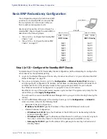
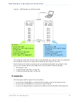
Heartbeats are detected primarily over the IP network as a result of your configuration that establishes
connectivity through the active and standby management ports (as described in “Basic BNP
Redundancy Configuration” on page 96).
If the network connection to the 10/100 control port on the active chassis fails, both chassis will have
the same output. Because this can be confusing to the network, and to ensure continuous healthy
operations, Imagine Communications recommends that you also set up a direct connection between
the active and standby GigE 8 ports, as described in “Configuring GigE Ports for Heartbeat Detection”
Before You Begin
Prior to setting parameters for 1:1 BNP system redundancy, please review the caveats provided in the
following topics:
•
“Conditions and Restrictions,” next.
•
“1:1 Redundancy Best Practices and Considerations” on page 94.

