Selenio
TM
VMG-14+ Hardware Setup Guide
25
Network Processor Modules
Gen2 Release 1.4.0
Note:
For a list of SFP and XFP modules approved for use with the NPM or NPM2, please refer to the
VMG release notes and/or Imagine Communications Customer Portal.
NPM
and
NPM2
Management
and
Serial
Ports
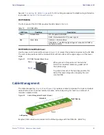
The NPM and NPM2 provides one 10/100BaseT Ethernet interface with an RJ-45 connector, compliant
with IEEE-802.3ab. A serial console port with an RJ-11 connector is also provided.
Serial
Console
Configuration—NPM
and
NPM2
•
19200 baud
•
No parity
•
8 data bits
•
1 stop bit
•
no flow control
Serial
Port
Pinouts—NPM
and
NPM2
Status
Red
Chassis interface is in fault state.
Green
NPM payload powered and out of reset.
Config
Red
FPGA configuration in progress.
Green
FPGA configuration is done.
Fault
Red
Fault.
Green
In normal operation.
Backup
Red
Standby.
Green
In operation.
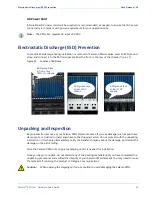
Table 8.
NPM Front Panel LED Description (Continued)
LED Name
Color/Condition
Description
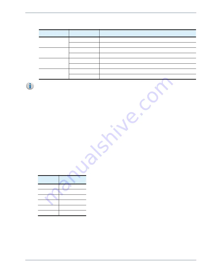
Table 9.
NPM Serial Reference
Pin
Number
Name
1
No Connect
2
TXD
3
RXD
4
No Connect
5
GND
6
No Connect


