Selenio
TM
VMG-14+ Hardware Setup Guide
40
Installation Instructions
Gen2 Release 1.4.0
Caution:
Do NOT use module handles to lift the VMG system. The handles provided on the fan trays,
PEMs, or cable trays cannot support the weight of the chassis.
Inspect
Contents
The Selenio VMG chassis ships with blank cards loaded in the rear slots. The power modules, fan trays,
and shelf control module cards are pre-loaded. All network and application modules are separately
packed. Check to ensure that your shipping carton contains the following components, as compliant
with your order:
•
System modules, as ordered, and front filler cards (as appropriate).
Each module is packed separately in your Selenio VMG shipping carton. Do not insert the network
or application modules until the chassis is rack mounted.
•
Power Supply Modules (PEMs): either AC or DC:
-
For DC: Up to four Power Entry Modules (PEMs), and a DC terminal block cover for each.
-
For AC: Up to four power supply units and up to four AC PEMs.
PEMs are typically pre-loaded in the chassis and should not be removed except for servicing.
•
Two front fan trays (each containing six fans).
The fan trays are typically pre-loaded in the chassis and should not be removed except for
servicing.
•
Up to two Shelf Control Managers (SCMs).
The SCMs are typically pre-loaded in the chassis and should not be removed except for servicing.
•
14 Rear Transition Module (RTM) Filler Panels.
The RTMs are always pre-loaded in the chassis and should never be removed.
•
One serial cable with serial connector.
•
One chassis support shelf.
•
Packaging.
Verify
Receipt
After removing the shipping contents from the carton, compare the contents of the shipping container
against the packaging list to ensure you have received all components required for your installation of
the Selenio VMG.
•
If any components are missing, contact your Imagine Communications representative.
•
If you need assistance, use the contact information provided in
“Technical Assistance” on page 11
.
Installation
Instructions
Installation of a new VMG system typically encompasses the tasks described in the following topics:
•
in next section
•
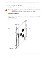
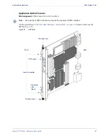
“Loading the Application Modules” on page 47
•
“Installing the Chassis at the Operations Rack” on
page 41
•
“AMP-to-NPM Cabling” on page 49
•
“Inserting VMG Modules—New System” on
page 41
•
“Double-Checking the Physical Installation” on
page 50
•
“Preparing the Power Supply (For DC)” on page 42
•
“Power Up and Verify” on page 50
•

