Selenio
TM
VMG-14+ Hardware Setup Guide
33
Cable Management
Gen2 Release 1.4.0
“Connecting DC Cables” on page 43
for DC cabling procedures. Troubleshooting information
is provided in
Chapter 5, “DC Power Servicing.”
DC
PEM
LEDs
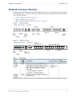
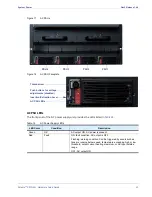
The front panel of the DC PEM provides the LEDs listed in
DC
PEM
Terminal
Block
Cover
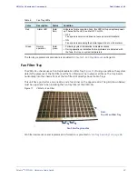
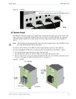
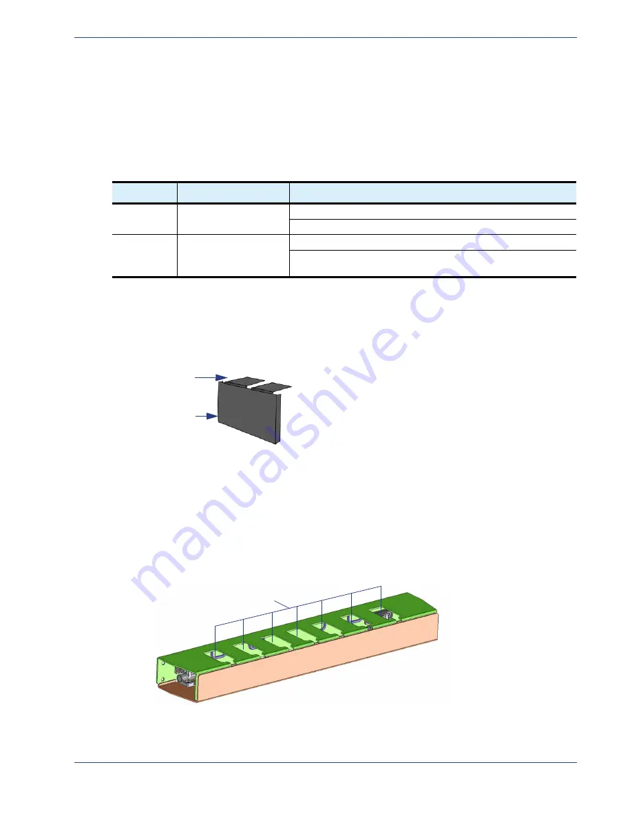
Use the snap-on DC terminal block cover (
) to protect the cabled connectors on the DC PEM.
The unit can be positioned at the terminal block with tabs either at the upper edge, or at the lower
edge.
Figure 21.
DC PEM Terminal Block Cover
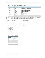
Cable
Management
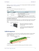
) provides a means to organize the input and output
cables that connect to various installed modules, without impeding the insertion or removal of
modules in adjacent slots.
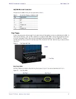
Figure 22.
Cable Management Bracket (closed)
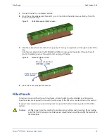
Imagine Communications recommends the following usage with the VMG-14+ Cable Tray
Table 15.
DC PEM LEDs
LED Color
Condition
Description
Green
Service state
Off - No power to the PEM.
Solid - Normal operation: DC power is good.
Red
Alarm state
Solid red = Error condition.
Solid Amber = -48 VDC supply voltage not connected to PEM, or
fan failure on PEM.
Tabs
Front
When placed in this position at the terminal
block, the connected cables are guided out of
the bottom edge.
To guide cables out of the top edge, position the
tabs at the lower edge when snapping the unit
into the PEM.
Left Opening
Right Opening
U-brackets
Front


