Selenio
TM
VMG-14+ Hardware Setup Guide
43
Installation Instructions
Gen2 Release 1.4.0
See
“Localized Cautions and Warnings” on page 74
to read translations for all Warnings applied in this
manual.
Grounding
the
Chassis
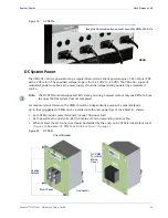
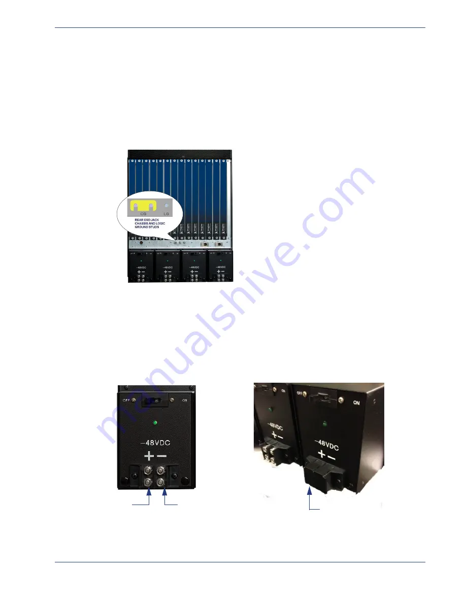
The Selenio VMG provides a chassis and logic ground terminals—labelled
CG and LG (
)—at
the rear of the chassis. The CG terminal provides two threaded screws (10-32 UNF) with a 15.88 mm
(.625 in.) spacing between thread centers to connect a double lug Shelf ground terminal cable.
Figure 27.
Chassis (rear) Ground and Logic Ground—DC System
Connecting
DC
Cables
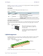
Each DC PEM provides two pairs of 1/4” studs (1/4 - 20 UNC) for
Return
and for
48V DC (
).
See
for cable specifications appropriate for use with these studs. Use
the snap-on DC PEM terminal block cover provided by Imagine Communications to protect cabled DC
connectors.
Figure 28.
DC PEM Cable Connectors
Use your site guidelines to determine the
site grounding point for the chassis.
Return (black)
-48V DC (red)
Connectors Exposed
DC PEM Terminal Block Cover
Connectors Shielded:

