18
VTM6801
+
Installation and Operation Manual
Chapter 3: Operation
Operating Notes
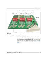
You can affect the composite output of each of the three channels by
adjusting the DIP switches for each channel. Each of the three banks of
DIP switches has the following five controls:
for specific instructions for setting the DIP switches and
monitoring the LEDs.
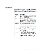
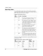
Table 3-1. DIP Switch Functions
DIP
Switch
Function
Description
1
STD
This setting controls standard selection. You can
set this switch for either NTSC or PAL-B.
2
VBI
This setting controls vertical blanking. You can
set this switch for either pass or blank. A blank
setting results in blanking lines 10 to 19 and 273
to 282 in NTSC operation and lines 6 to 22 and
319 to 335 in PAL operation.
3
Setup
This setting controls setup (pedestal) in NTSC
operation. When the channel is set to PAL
operation, this switch has no effect.
4
Test
This setting controls color bars test signal. You
can set this switch so that the color bars test
signal is displayed at the composite output (100/
7.5/75/7.5 for NTSC and 100/0/77/0 for PAL).
This feature requires valid CCIR-601 4:2:2 video
data input.
5
B&W
This setting controls black and white output. You
can remove the chrominance and burst from the
channel, thereby creating black and white output.
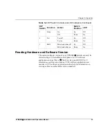
Table 3-2. DIP Switch Controls and LED Indicators
DIP
Switch
Function
Action
Switch
Position
LED
1
STD
NTSC
Up
Off
PAL
Down
On
2
VBI
Pass
Up
Off
Blank
Down
On

