background image

DFK 33UX252 Technical Reference Manual

3

Table of Contents

Trigger Mode  ......................................................................................................... 26

5.4.1

Trigger Polarity  ...................................................................................................... 26

5.4.2

Software Trigger  .................................................................................................... 27

5.4.3

Trigger Exposure Mode .......................................................................................... 27

5.4.4

Trigger Burst Count ................................................................................................ 27

5.4.5

Trigger Source ........................................................................................................ 28

5.4.6

Trigger Overlap ...................................................................................................... 28

5.4.7

IMX Low-Latency Mode  ......................................................................................... 28

5.4.8

5.5

Trigger Timing Parameters .......................................................................................... 29

Trigger Delay  ......................................................................................................... 29

5.5.1

Trigger Debounce Time  ......................................................................................... 30

5.5.2

Trigger Mask Time ................................................................................................. 30

5.5.3

Trigger Noise Suppression Time ............................................................................ 30

5.5.4

5.6

Digital I/O ..................................................................................................................... 31

General Purpose Input  ........................................................................................... 31

5.6.1

General Purpose Output  ........................................................................................ 31

5.6.2

5.7

Strobe ........................................................................................................................... 32

Strobe Enable ......................................................................................................... 32

5.7.1

Strobe Polarity ........................................................................................................ 32

5.7.2

Strobe Operation .................................................................................................... 33

5.7.3

Strobe Duration ...................................................................................................... 33

5.7.4

Strobe Delay ........................................................................................................... 34

5.7.5

5.8

White Balance .............................................................................................................. 34

Auto White Balance ............................................................................................... 34

5.8.1

White Balance Mode  ............................................................................................. 35

5.8.2

Manual White Balance  .......................................................................................... 35

5.8.3

5.9

Image Processing ......................................................................................................... 37

Gamma ................................................................................................................... 37

5.9.1

Lookup Table .......................................................................................................... 38

5.9.2

5.10

Color Processing ........................................................................................................... 39

Hue ......................................................................................................................... 39

5.10.1

Saturation ............................................................................................................... 40

5.10.2

5.11

Region of Interest for Auto Functions ....................................................................... 40

Auto Functions ROI Enable  .................................................................................... 40

5.11.1

Auto Functions ROI Preset ..................................................................................... 40

5.11.2

Auto Functions ROI Custom Rectangle .................................................................. 41

5.11.3

5.12

User Sets ....................................................................................................................... 42

User Set Selector .................................................................................................... 42

5.12.1

Load User Set ......................................................................................................... 42

5.12.2

Save User Set  ......................................................................................................... 43

5.12.3

Default User Set ..................................................................................................... 43

5.12.4

5.13

Multi-Frame Output Mode ......................................................................................... 43

Multi-Frame Output Mode Enable ......................................................................... 43

5.13.1

Summary of Contents for DFK 33UX252

Page 1: ...DFK 33UX252 Technical Reference Manual...

Page 2: ...vity IMX252LQR C 13 5 Camera Controls 14 5 1 Sensor Readout Control 14 Pixel Format 14 5 1 1 8 Bit Bayer Raw 15 5 1 1 1 16 Bit Bayer Raw 15 5 1 1 2 YUV 4 2 2 15 5 1 1 3 YUV 4 1 1 16 5 1 1 4 RGB24 16 5...

Page 3: ...robe 32 Strobe Enable 32 5 7 1 Strobe Polarity 32 5 7 2 Strobe Operation 33 5 7 3 Strobe Duration 33 5 7 4 Strobe Delay 34 5 7 5 5 8 White Balance 34 Auto White Balance 34 5 8 1 White Balance Mode 35...

Page 4: ...e Manual 4 Table of Contents Multi Frame Output Mode Frame Count 44 5 13 2 Multi Frame Output Mode Exposure Time 44 5 13 3 Multi Frame Output Mode Custom Gain 45 5 13 4 Multi Frame Output Mode Gain 45...

Page 5: ...r RG RGB24 YUV 4 2 2 YUV 4 1 1 Optical Interface IR Cut filter Yes Sensor Type Sony IMX252LQR C Shutter Type Global Sensor Format 1 1 8 inch Pixel Size 3 45 m Lens Mount C CS Electrical Interface Inte...

Page 6: ...nual 6 Quick Facts Adjustments Shutter 20 s to 4 s Gain 0 dB to 48 dB Environmental Temperature operating 5 C to 45 C Temperature storage 20 C to 60 C Humidity operating 20 to 80 non condensing Humidi...

Page 7: ...DFK 33UX252 Technical Reference Manual 7 Dimensional Diagrams 2 Dimensional Diagrams 2 1 DFK 33UX252 C Mount with Tripod Adapter...

Page 8: ...DFK 33UX252 Technical Reference Manual 8 Dimensional Diagrams 2 2 DFK 33UX252 C Mount without Tripod Adapter...

Page 9: ...DFK 33UX252 Technical Reference Manual 9 Dimensional Diagrams 2 3 DFK 33UX252 CS Mount with Tripod Adapter...

Page 10: ...DFK 33UX252 Technical Reference Manual 10 Dimensional Diagrams 2 4 DFK 33UX252 CS Mount without Tripod Adapter...

Page 11: ...n c 5 n c 6 n c 7 GND_I O G3 External Ground 8 n c 9 n c 10 STROBE_OUT O3 Open drain 24 01 V 11 TRIGGER_IN I3 Optocoupler signal 3 32 24 02 V 12 TRIGGER_IN I3 Optocoupler ground 1 max 0 2A ID for open...

Page 12: ...olled The current input signal can also be read directly through the General Purpose Input feature 3 1 2 STROBE_OUT The STROBE_OUT line s main usage is to indicate the integration time of the image se...

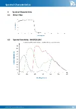
Page 13: ...DFK 33UX252 Technical Reference Manual 13 Spectral Characteristics 4 Spectral Characteristics 4 1 IR Cut Filter 4 2 Spectral Sensitivity IMX252LQR C...

Page 14: ...Vision the pixel format is controlled through the PixelFormat GenICam feature When using the uvcvideo driver on Linux the pixel format is defied by video4linux2 When using IC Imaging Control the pixe...

Page 15: ...the data as if the sensor outputs 16 bits USB3 Vision drivers see this pixel format as one of the 16 bit packed bayer raw formats BayerGR16 BayerRG16 BayerGB16 BayerBG16 UVC drivers see it with the F...

Page 16: ...mat thus reducing the maximum possible frame rate USB3 Vision drivers enumerate this pixel format as BGR8 UVC drivers see it with the FourCC RGB24 The Device Driver for The Imaging Source USB 33U 37U...

Page 17: ...s the image sensor regularly skips a number of rows and or columns during readout The resulting output image is smaller but contains the same field of view than the image produced by default readout m...

Page 18: ...tionFrameRate When using uvcvideo on Linux the frame rate is selected from a list of available frame rates When using IC Imaging Control the frame rate is selected from a list of available frame rates...

Page 19: ...01 YUV 4 2 2 Width Height Maximum Frame Rate 2048 1536 60 1920 1080 91 640 480 601 YUV 4 1 1 a Width Height Maximum Frame Rate 2048 1536 80 1920 1080 121 640 480 608 YUV 4 1 1 b Width Height Maximum F...

Page 20: ...the offsets so that the center of the sensor is used Parameter Partial Scan Offset X Minimum 0 Maximum 1792 USB3 Vision GenICam OffsetX Video4Linux2 ROI Offset X VCD Property VCDID_PartialScanOffset...

Page 21: ...or both The Flip Horizontal and Flip Vertical parameters can be used to control this sensor feature Parameter Flip Horizontal True Image data is flipped horizontally False Image data is not flipped h...

Page 22: ...mplification that is applied to the image at sensor level Parameter Gain Minimum 0 dB Maximum 48 dB Default auto USB3 Vision GenICam Gain Video4Linux2 Gain db 100 VCD Property VCDID_Gain VCDElement_Va...

Page 23: ...to controlled parameters For example one might want to avoid high gain settings in order to keep noise levels low Other applications require limiting the maximum exposure time so that movements do not...

Page 24: ...10 12 16 bit output images and a tone mapping algorithm in post processing when using higher bit depths as the dark areas still contain a lot of useful information Parameter Highlight Reduction True...

Page 25: ...possible value for the current frame rate Parameter Auto Exposure Upper Limit Auto On Select Auto Exposure Upper Limit automatically Off Let the user control Auto Exposure Upper Limit USB3 Vision Gen...

Page 26: ...enables the trigger mode Parameter Trigger Mode On Enable Trigger Mode True Off Disable Trigger Mode False USB3 Vision GenICam TriggerMode Video4Linux2 Trigger Mode VCD Property VCDID_Trigger VCDEleme...

Page 27: ...ime parameter The exposure time can also be controlled by the time the TRIGGER_IN line is kept in active state Parameter Trigger Exposure Mode FrameStart The exposure time is controlled by the Exposur...

Page 28: ...ardware trigger Software Allow only software trigger USB3 Vision GenICam TriggerSource 5 4 7 Trigger Overlap The Trigger Overlap feature gives information on when a new trigger pulse is accepted in th...

Page 29: ...options for dealing with bad trigger signals By using the Debounce Time Denoise Time and Mask Time parameters the camera can be configured to ignore pulses on its TRIGGER_IN line under certain conditi...

Page 30: ...me us VCD Property VCDID_Trigger VCDElement_TriggerDebouncer 5 5 3 Trigger Mask Time The Trigger Mask Time parameter specifies the time for which trigger pulses are ignored after accepting a trigger s...

Page 31: ...he digital output can be configured as a Strobe output to signal the exact moment when the image sensor is sensitive to light so that external light sources can be synchronized to its operation cycle...

Page 32: ...unction controls the automatic generation of output pulses on the STROBE_OUT pin which is synchronized to the image sensor s exposure time 5 7 1 Strobe Enable The Strobe Enable parameter enables the a...

Page 33: ...e strobe pulses are controlled Parameter Strobe Operation Exposure Output pulse duration is equal to the current exposure time True FixedDuration Output pulse duration is specified by Strobe Duration...

Page 34: ...es in lighting conditions are expected Under controlled lighting conditions however one time white balance calibration is the recommended approach To perform one time white balance calibration place a...

Page 35: ...ance Mode Gray World Use the Gray World model Temperature Use the Temperature model USB3 Vision GenICam BalanceWhiteMode Video4Linux2 Whitebalance Mode VCD Property VCDID_WhiteBalance VCDElement_White...

Page 36: ...uto USB3 Vision GenICam BalanceRatio BalanceRatioSelector Green Video4Linux2 White Balance Green Component VCD Property VCDID_WhiteBalance VCDElement_WhiteBalanceGreen Parameter White Balance Blue Min...

Page 37: ...K Neutral White 3500 K Cool White Fluorescent Light 4000 K Cool White Daylight CFL 5000 K Daylight 6000 K Cool White LED 7500 K Blue Sky 10000 K USB3 Vision GenICam BalanceWhiteTemperaturePreset Video...

Page 38: ...e is applied only to the Y channel In bayer raw and RGB24 modes all color channels are subject to the same lookup operation The lookup table has 257 16 bit entries The upper 8 bits of the image data a...

Page 39: ...rrection is disabled when the lookup table is enabled 5 10 Color Processing The DFK 33UX252 color camera allows color adjustments with the Hue and Saturation parameters These adjustments work with all...

Page 40: ...is used while controlling the Auto Exposure Auto Gain and Auto White Balance functions 5 11 1 Auto Functions ROI Enable The Auto Functions ROI Enable parameter allows for the use of a region of inter...

Page 41: ...OI Preset VCD Property VCDID_AutoRoi VCDElement_AutoRoiPreset 5 11 3 Auto Functions ROI Custom Rectangle When Auto Functions ROI Preset is set to Custom Rectangle the user can manually set the positio...

Page 42: ...can be saved into and restored from one of two available memory slots upon user s request Additionally the camera can be configured to load one of the user s camera configurations at startup 5 12 1 U...

Page 43: ...tion when the camera is powered up Parameter Default User Set UserSet1 Load configuration from the first memory slot UserSet2 Load configuration from the second memory slot Default Load factory defaul...

Page 44: ...se two different exposure times 4 Frames Use four different exposure times USB3 Vision GenICam MultiFrameSetOutputModeFrameCount VCD Property VCDID_MultiFrameOutputMode VCDElement_MultiFrameCount 5 13...

Page 45: ...tiFrameSetOutputModeCustomGain VCD Property VCDID_MultiFrameOutputMode VCDElement_MultiFrameCustomGainEnable 5 13 5 Multi Frame Output Mode Gain The Multi Frame Output Mode Gain parameters controls th...

Page 46: ...DFK 33UX252 Technical Reference Manual 46 Revision History 6 Revision History Date Version Description 2018 04 19 Initial release of this document...

Page 47: ...ng Source Company reserves the right to make changes in specifications function or design at any time and without prior notice Last update April 2019 2019 The Imaging Source All rights reserved Reprin...

Reviews: