background image

Warranty    

41

13    Warranty

IMANTS BV warranty information

(A) Warranty

IMANTS BV guarantees that none of the products that it manufactures has any material faults and IMANTS BV issues
a warranty for the manufactured products at the time of shipment, which is valid for a period of twelve (12) months from
the date of delivery to the customer. IMANTS BV delivers replacement parts, free of charge, for all parts that IMANTS
BV considers to be faulty at the time of shipment. Alternatively, IMANTS BV can opt to repair such components or have
such components repaired on its behalf on the condition that such components are returned on request to the factory
at Turnhoutseweg 29, 5541 NV, Reusel, the Netherlands. The transport costs for the return shipment must be paid in
advance.

This warranty does not apply to any products that have been subject to incorrect use, incorrect application, negligence
(including, but not limited to, incorrect maintenance), an accident, incorrect installation, a modification (including, but not
limited to, the use of components or add-on components for which permission has not been granted), an alteration or
repair. Motors and all accessories that are delivered with products from IMANTS BV but which are not manufactured
by IMANTS BV are not covered by the warranty issued by IMANTS BV. They are only sold with the explicit warranty, if
there is one, issued by the manufacturer concerned. THE ABOVE REPLACES ALL OTHER WARRANTIES, EITHER
EXPLICITLY OR IMPLICITLY (INCLUDING GUARANTEES OF SALEABILITY AND SUITABILITY OF ANY PRODUCT
FOR A CERTAIN PURPOSE), AS WELL AS ANY OTHER LIABILITY OF IMANTS BV.

(B) Limitation of liability

It is expressly stated that the liability of IMANTS BV for its products, either on account of termination of the warranty,
negligence, strict liability or otherwise, is limited to the delivery of replacement components and that IMANTS BV is
not liable for any injury, loss, damage or expenses, neither directly or indirectly, including, but not limited to, a loss of
use, income, profit or production, or higher operational costs, or decay or damage of materials resulting from the sale,
installation, use, inability to use, or repair or replacement of IMANTS BV products.

Every operation that is expressly forbidden in the operating instructions or instruction manuals that are provided with
the machine, and any alteration or assembly procedure that is not recommended by or is not permitted according to the
operating or maintenance instructions invalidates such warranty.

(C) Registration

THIS WARRANTY IS INVALID UNLESS THE REGISTRATION FORM IS COMPLETEED AND RETURNED TO
THE FACTORY AT TURNHOUTSEWEG 29, 5541 NV, REUSEL, THE NETHERLANDS, WITHIN 30 DAYS AFTER
DELIVERY OF THE UNIT TO THE CUSTOMER.

No component must be returned under warranty unless IMANTS BV has given permission for it to be returned (RGA -
Return Goods Authorization).

ALWAYS STATE THE NAME OF THE COMPONENT, THE COMPONENT NUMBER AND THE SERIAL NUMBER OF
THE MACHINE WHEN ORDERING COMPONENTS.

COMMENT:

IMANTS BV maintains the right to make changes to the design and construction without the obligation to also make
these changes to previously sold products. In the event of conflicts, the general terms and conditions of delivery and
payment laid down by the Koninklijke Metaalunie are applicable.

Summary of Contents for ShockWave 100

Page 1: ...ShockWave 100 155 210 Manual 998 094 2 Original document...

Page 2: ...contact your supplier s service department This document has been produced with the greatest of care Imants BV cannot however accept any responsibility for any errors in this document or any conseque...

Page 3: ...ons about your 100 155 210ShockWave or wish to order parts those specific details will allow us to help you quickly and efficiently Carefully read the full contents of this document A failure to do so...

Page 4: ......

Page 5: ...8 5 1 ShockWave 18 6 Loading and unloading the machine 19 7 Putting the machine into operation 20 7 1 Putting the PTO shaft into operation 21 8 Transport 22 9 Working with the machine 23 9 1 Tractor s...

Page 6: ...Table of contents 6 10 4 1 ReplaceAeration blade 38 11 Cleaning 39 12 Decommissioning 40 13 Warranty 41 14 Appendix Appendices 42 15 CE declaration 43...

Page 7: ...tructions before using the machine for the first time The illustrations used in this Manual may differ from the configuration of your machine they are merely intended to explain a working principle Pl...

Page 8: ...in this manual Symbols have also been applied to the machine In this chapter you can see what these pictograms and symbols mean what they refer to or what they are warning you about 2 1 1 Hazard indi...

Page 9: ...ion Gloves Eye protection Clothing stipulations Document reference Use of tools Material use Read the manual Danger of becoming trapped due to being present within the lifting range Danger of becoming...

Page 10: ...low includes all possible pictograms which does not mean they are all used in this Manual On Off Hitch tension adjustment Hitch position adjustment Hitch downwards Hitch upwards Hitch working depth Pr...

Page 11: ...he purpose it was designed for The machine may only be used and maintained by persons who are familiar with the machine and have been made aware of the risks No one who could not be expected to make c...

Page 12: ...e machine has been properly supported For reasons of quality and safety only use original Imants parts Maintain the machine as indicated later in the manual Only perform this work when the machine is...

Page 13: ...ly being started and rolling away while work is being carried out on the machine such as installation set up troubleshooting cleaning maintenance and repair work There is a risk of serious injury or e...

Page 14: ...arning stickers and type plate on the machine Warning labels should always be legible The illustration below shows where the safety stickers and type plate are to be found on the machine Illustration...

Page 15: ...always be trained and qualified to operate the machine remain alert and avoid hazardous situations always conduct an inspection before use conduct functional tests check the workplace keep bystanders...

Page 16: ...exercise the greatest caution when working Even if all the safety precautions are taken and the machine is used in accordance with the regulations there are still residual risks Residual risks Contact...

Page 17: ...1 Machine parts and drive Depending on the model the machine functions are as follows Restoring maintaining stretches of grass A tractor provides the power needed to drive and tow the machine The pow...

Page 18: ...42 3 Centre of gravity distance mm 635 25 635 25 635 25 Weight Machine weight kg lbs 475 1045 580 1276 630 1386 Working speed Max working speed Km h mph 1 5 0 9 1 5 0 9 1 5 0 9 Working depth Max work...

Page 19: ...proved lifting equipment wire ropes belts chains etc that have a permissible load that is greater than the weight of the machine see type plate do not have any defects Only qualified personnel should...

Page 20: ...load clutch according to the instructions provided by the manufacturer of the PTO drive shaft Check whether the clearance around the PTO drive shaft is sufficient whatever the operating conditions The...

Page 21: ...heid de downloads anleitungen Points of attention 1 The length of the PTO shaft With the shortest operating distance between the tractor and the machine the PTO shaft must still be able to slide in by...

Page 22: ...on could include matters such as Maximum transport width Maximum axle load Lighting to be shown Use of warning signs Before the tractor machine combination goes on a public road at least check the fol...

Page 23: ...tch pedal nor take the tractor out of gear The machine could actually push the tractor forward This could lead to hazardous situations It is not permitted to stand on the machine or to stand within th...

Page 24: ...Working with the machine 24 Immediately turn off the PTO if the raised machine runs erratically Friction with the soil may cause the wear parts to become very hot...

Page 25: ...ings Ensure there is sufficient weight at the front of the tractor Ensure the tyre pressures are equal Place the lifting arms at the same height Put the lowering speed of the hitch to slow Select the...

Page 26: ...ing or rolling away 6 Connect the PTO shaft 7 Reverse further with the tractor towards the machine 8 Connect the three point hitch to the machine s coupling points Ensure the coupling points are prope...

Page 27: ...must have come to a complete standstill The tractor s engine must be switched off and the key must have been removed from the ignition Procedure Illustration 1 Disassemble the running roller Pay atte...

Page 28: ...nner pack Procedure Illustration 1 Raise the machine 2 During all operational activities make sure the machine cannot roll away unintentionally 3 Secure the tractor to prevent unintended starting or r...

Page 29: ...the PTO just before the rotor contacts the ground 6 Gradually increase the engine speed and the driving speed Optimum driving speed 7 After 20 metres check the machine s working depth 8 If the working...

Page 30: ...Working with the machine 30 If present Optional...

Page 31: ...l mechanical hydraulic pneumatic and electrical energy present in the machine The machine may come to a halt because it is full or because of stones or other obstacles To prevent damage to the transmi...

Page 32: ...l energy present in the machine 1 Lower the machine s support legs and secure them again with a linch pin 2 Place the machine on a flat stable surface 3 Secure the tractor to prevent unintended starti...

Page 33: ...id dangerous situations Repair broken or worn parts before using the machine Be aware of residual mechanical hydraulic pneumatic and electrical energy present in the machine Work may only be carried o...

Page 34: ...rises the following components 10 2 1 PTO drive shaft Keep the PTO drive shaft clean Lubricate sliding parts so that the PTO drive shaft can slide in and out easily Consult the PTO shaft manual for it...

Page 35: ...responsible manner To do so follow the local statutory regulations in force Check the oil level 1 Set the gear box to be horizontal 2 The oil level must be in the middle of the sight glass of the lev...

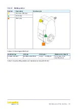
Page 36: ...pe Vent plug filler plug Level plug Drain plug Table 4 Oil level legend6020 M 1 Gearbox type Oil type Oil volume Maintenance interval 010963 6020 M 1 MobilGear 600XP320 3 5 L 0 9 USgal 12 months or 50...

Page 37: ...the machine 37 10 3 Periodic maintenance and inspection Checking the vent nipples Symbol Number of bleed nipples Maintenance interval 1 Main gearbox 12 months or 500 operating hours Table 6 Checking t...

Page 38: ...oved from the ignition For reasons of quality and safety only use original Imants parts Dispose of any worn components in an environmentally responsible manner Always follow the locally applicable sta...

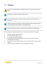
Page 39: ...r or fat soluble agents Observe the legal requirements concerning the use and disposal of cleaning agents When cleaning with a high pressure cleaner you must always follow the instructions below 1 Max...

Page 40: ...hen the machine is decommissioned the parts can be sorted as follows 1 Metals 2 Plastics 3 Oils and greases Dispose of the sorted materials in an environmentally responsible manner Always follow the l...

Page 41: ...T FOR A CERTAIN PURPOSE AS WELL AS ANY OTHER LIABILITY OF IMANTS BV B Limitation of liability It is expressly stated that the liability of IMANTS BV for its products either on account of termination o...

Page 42: ...Appendix Appendices 42 14 Appendix Appendices In this part of the manual you can find extra information about your machine...

Page 43: ...CE declaration 43 15 CE declaration...

Page 44: ...Imants BV Turnhoutseweg 29 5541 NV Reusel 31 0 497 642 433 31 0 497 643 205 www imants nl info imants nl...

Reviews: