v
Daily history report through e-mail
v
Address-specific IP security masks to prevent unauthorized access
Hardware components
The following sections provide descriptions of the front and rear components on the
PDU.
Front view
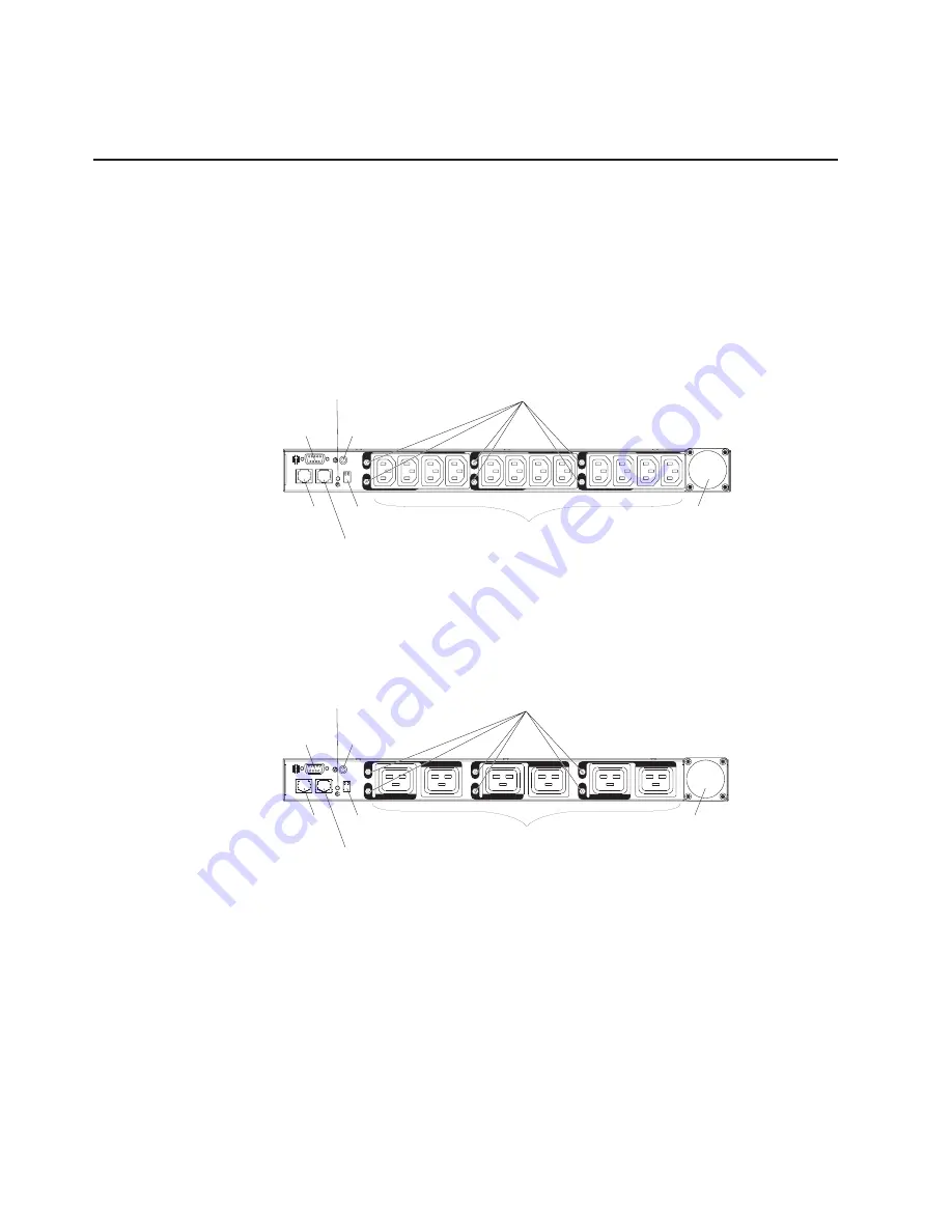
The following illustration shows the components and controls on the front of the DPI
C13 PDU+ and the DPI C13 3-phase PDU+.
Note:
The DPI C13 3-phase PDU+ comes with an attached power cord.
LA
N
5
6
RS-232 serial
connector
LED
RJ-45 LAN
connector
RJ-45
console connector
Operation
mode DIP switch
Input power
connector
Power outlets
2
1
3
4
Circuit breakers
Reset button
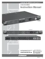
The following illustration shows the components and controls on the front of the DPI
C19 PDU+ and the DPI C19 3-Phase PDU+.
Note:
The DPI C19 3-Phase PDU+ comes with an attached power cord.
5
6
3
4
LA
N
1
2
RS-232 serial
connector
LED
Circuit breakers
RJ-45 LAN
connector
RJ-45
console connector
Operation
mode DIP switch
Power outlets
Input power
connector
Reset button
RS-232 serial connector
Use the RS-232 serial connector to update the PDU firmware.
Reset button
Use this button to reset the PDU for communication purposes only.
Resetting the PDU does not affect the loads.
LED
The green LED shows the PDU input voltage status. When this LED is lit,
the PDU is receiving voltage. If the input voltage is too low, this LED is
flashing.
Circuit breakers
If the load current rating for a power outlet exceeds 20 A, the associated
circuit breaker is activated (the breaker pole pops out) and power to the
6
DPI C13 PDU+, DPI C13 3-phase PDU+, DPI C19 PDU+, and DPI C19 3-phase PDU+: Installation and Maintenance Guide


