background image

11

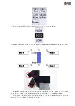
2.2 Motor speed control button (same as P-01 in 6.2.1 setting menu)。

2.3 Blower, cutting stitches:Click the number to change the corresponding parameter value。

Blow 1&2:Blowing operation, bottom line off line,When the pants cover the first piece

of reflective paper, stop blowing according to the number of delayed stitches;

Front cut:The pants cover the second piece of reflective paper and start cutting

according to the number of delayed stitches;

Blow 1

Blow 3

Blow 2

Blow 4

Summary of Contents for MB2003D-KS-1509P

Page 1: ...CHANGZHOU WISDOM VALLEY ELECTRICAL TECHNOLOGY CO LTD Please read the operation manual of the touch screen interface before using the device Please keep this operation manual of touch screen interface...

Page 2: ...comply with current regulations IMB No part of this manual may be copied or transcribed without requesting prior authorization from IMB The contents of this manual may be subject to change without adv...

Page 3: ...ENGLISH...

Page 4: ...ion 9 6 2 Parameter setting 9 6 3 Front and rear roller pressure 12 6 4 Speed ratio between roller and feed dog 13 6 5 Position of upper and lower roller baffle 14 6 6 Cutter change 15 7 Electrical wi...

Page 5: ...1 1 Basic information of equipment 1 KS 1509P machine head 2 Touch screen 3 Control box 4 Table 5 Pedal 6 Puller 5 1 4 3 2 6...

Page 6: ...setter 1 Machine head KS 1509P 2 Maximum sewing speed rpm 4000 3 Working voltage V 220 4 Pressure Mpa 0 5 5 Stitch length mm 2 5 6 waist width range mm 30 43 7 Suitable fabric Denim 8 waist type Stra...

Page 7: ...f the power or air supply while the machine is running 8 In order to prevent accidents caused by sudden starting please remove the cloth guide when the preparation work is finished and the sewing stat...

Page 8: ...ine important safety information improper operation of the machine may cause personal injury Please read this instruction carefully and operate correctly before operation Please ventilate the machine...

Page 9: ...on 1 Power switch press the power switch to position 1 and the equipment is powered on and ventilated 2 Foot pedal front step sewing back step presser foot lift 3 Pressure reducing valve adjust the cy...

Page 10: ...e rear tugboat on the right side 4 Hand slide valve when the presser foot is raised the sliding hand slide valve controls the lifting and landing of the front tug and the front tug normally falls down...

Page 11: ...d 5 2 Description of operation process 1 Start the device Press the power switch To position 1 Power on the equipment Select the language in the 4 1 5 a boot interface and enter the 4 1 5 B monitoring...

Page 12: ...8 b Curved The sewing procedure is the same as straight waist 3 Shut down Press the power switch To position 0 the device is shut down...

Page 13: ...ace Laser Cover reflective paper corresponding button turn green laser normal Other signals Click Turn green The solenoid valve reacts and the electricity is normal 6 2 Parameter setting 1 Click the m...

Page 14: ...ning stitches Adjust the up blowing time P 05 P 06 Intermittent Blower opening closing stitches A loose thread is needed in the middle of the sewing The number of stitches can be set according to the...

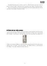
Page 15: ...nding parameter value Blow 1 2 Blowing operation bottom line off line When the pants cover the first piece of reflective paper stop blowing according to the number of delayed stitches Front cut The pa...

Page 16: ...ont and rear roller pressure 1 Front roller pressure Manually rotate the pressure regulating knob of the left pressure reducing valve as shown in the figure below The pressure of the roller is maintai...

Page 17: ...pitch 2 Lower roller Adjust the position of both ends of the connecting rod in the figure below to adjust the speed of the lower roller Front roller The rotation speed of the rear tugboat can be adjus...

Page 18: ...er and lower roller baffle 1 Left inner baffle of front roller Loosen the fixing screw 1 so that the bottom edge of the baffle is close to the front roller Prevent the thread end and waist head from b...

Page 19: ...he upper cutter replace the new cutter and install the fixing screw 5 and tighten 3 Remove the two retaining screws 3 Remove the lower cutter replace the new cutter and install the fixing screw 3 No t...

Page 20: ...16 7 Electrical wiring 7 1 Electronic control...

Page 21: ...17 7 2 Pneumatic control...

Page 22: ...18 8 Optional devices 8 1 Stacker It is mainly suitable for continuous waist cutting...

Page 23: ...1 8 02200320105400 3 9 02200320105300 4 10 02200320105500 1 11 050200501013 4 12 01200320106100 1 13 012003230003 CLTB10 1 14 060202000043 M4 16 4 15 060204000047 M4 4 8 16 060202000040 M4 12 2 17 06...

Page 24: ...20 9 Accessory box details NO ITEM QTY 1 instruction manual 1 2 Parts Manual 1 3 Machine head accessory box 1 4 Front roller curved 1 5 Thread stand cover 1 6 Head cover plate 1...

Page 25: ...mb2003d waist pulling machine touch screen interface operation instructions to set the number of delayed blowing or cutting needles After the waist is sewn the upper and lower pieces are dislocated Th...

Page 26: ...e dust Remove dust on equipment surface and parts 2 Clean up the oil Clean the oil stains on the table board needle plate and shuttle core 3 oil quantity The oil quantity is not lower than the warning...

Page 27: ...ogy Co Ltd and are protected by national intellectual property laws and regulations Without the written permission of the right holder the patented technology of the achievement shall not be implement...

Reviews: