12
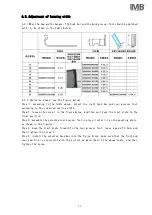
6.3. Adjustment of hemming width
6.3.1 When the hem width changes,The hook bar and the back presser foot should be matched
with it,As shown in the table below:
6.3.2 Operation steps (see the figure below)
Step 1: according to the table above, select the right hook bar and rear presser foot
according to the required curling width
Step 2: loosen the screw 1 in the figure below, and then pull back the Limit plate to the
final position
Step 3: assemble the selected rear presser foot in place (install it on the mounting plate,
as shown in the figure)。
Step 4: move the Limit plate forward to the rear presser foot, leave a gap of 0.2mm, and
then tighten the screw 1。
Step 5: install the selected hook bar into the fixing block, make sure that the front and
rear position is consistent with the picture as described in the above table, and then
tighten the screw
Summary of Contents for MB5004E-IM
Page 3: ......
Page 4: ...1 2 3 4 4 1 4 4 2 5 4 3 6 7 5 1 7 5 2 7 9 6 1 9 6 2 10 6 3 11 6 4 12 6 5 13 14 15 16 17...
Page 5: ...1 1 GC6770 2 3 4 5 6 7 8 9 10 11 12 2 3 1 4 5 6 11 9 8 10 7 12...
Page 7: ...3 1 1 2 V 3 4 5 6 7 8 9 10 11 12 13 14 A...
Page 8: ...4 4 1 1 90 ON 2 3 4 MB5004E IM 1 3 4 2...
Page 9: ...5 4 2 a b...
Page 10: ...6 ON ON 1 2 3 ON OFF OFF 1 2 3 ON OFF 1 2 1 2 3 4 4 3 1 2...
Page 11: ...7 5 1 5 2 5 2 1 90 ON 5 2 1...
Page 12: ...8 5 2 3 5 2 4 90 OFF...
Page 13: ...9 6 1 Mp 1 0 4 0 5 2 0 1 0 2 3 0 3 0 4 4 0 1 0 2 5 0 1 0 2 6 0 3 0 4...
Page 14: ...10 6 2 6 2 1 6 2 2...
Page 15: ...11 6 3 6 3 1 6 3 2 1 0 2mm 1 1 1 1...
Page 16: ...12 6 4 1 2 6 4 1 1 2 6 4 2 2...
Page 20: ...16 11 1 11 2 GC6770 C 1 2 3 4 5 6 7...
Page 21: ...17 MB5004E...
Page 22: ...ENGLISH...
Page 29: ...6 4 2 Operator interface description a Power on interface b Main interface...


