background image

3


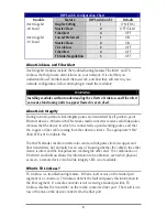
DIP Switch Configuration Chart 

Module 

Feature 

DIP Switch on S1 

Default 

Duplex Setting 

ON (FDX) 

Master/Slave 

OFF (Slave) 

iMcV-Gigabit 
-00 board 

FiberAlert 

OFF 

Forced/Preferred 

ON 

Master/Slave 

ON 

TX LinkLoss 

OFF 

FiberAlert 

OFF 

iMcV-Gigabit 
-10 board 

FX Auto-Negoitation 

OFF 

About LinkLoss and FiberAlert 

iMcV-Gigabit modules include the troubleshooting features FiberAlert  and TX 
LinkLoss that help locate 

silent failures

 on your network.  It is vital that you 

understand how FiberAlert and LinkLoss work, and how they will react in your 
network configuration, before attempting to install the module(s). 
 

WARNING  

Installing modules without understanding the effects of LinkLoss and FiberAlert 
can cause functioning units to appear flawed or even dead. 

About Link Integrity 

During normal operation, link integrity pulses are transmitted by all point-to-point 
Ethernet devices.  When an IMC Networks media converter receives valid link pulses, 
it knows that the device to which it is connected is up and sending pulses, and that 
the copper or fiber cable coming from that device is intact.  The appropriate “LNK” 
(link) LED is lit to indicate this. 
 
The IMC Networks media converter also sends out link pulses from its copper and 
fiber transmitters, but normally has no way of knowing whether the cable to the other 
device is intact and the link pulses are reaching the other end.  The combination of 
FiberAlert and LinkLoss allows this information to be obtained, even when physical 
access to a remote device (and its link integrity LED) is not available. 

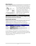
What is TX LinkLoss? 

TX LinkLoss is a troubleshooting feature.  When a fault occurs on the twisted pair 
segment of a conversion, TX LinkLoss detects the fault and passes this information to 
the fiber segment.  If a media converter is not receiving a twisted pair link, TX 
LinkLoss disables the transmitter on the media converter's fiber port.  The result is in a 
loss of the link on the device connected to the fiber port. 

Summary of Contents for iMcV-Gigabit

Page 1: ...iMcV Gigabit Operation Manual...

Page 2: ...er To receive in warranty service the defective product must be received at IMC Networks no later than the end of the warranty period The product must be accompanied by proof of purchase satisfactory...

Page 3: ...i Warranty i About the iMcV Gigabit 1 Configuration Instructions 2 Additional Gigabit Features 5 LED Operation 7 Installation Troubleshooting 8 Notes 9 IMC Networks Technical Support 10 Specification...

Page 4: ...ersion that allows two wavelengths to share one fiber strand Full Duplex data travels on different wavelengths 1310 nm and 1550 nm doubling the capacity of fiber Also one RJ 45 connector and one SC fi...

Page 5: ...ttings e g jumper switch etc so you must configure a module that will be managed via the software Until you configure a managed module via the software the module and its LEDs may not work properly Un...

Page 6: ...s When an IMC Networks media converter receives valid link pulses it knows that the device to which it is connected is up and sending pulses and that the copper or fiber cable coming from that device...

Page 7: ...rAlert and LinkLoss Modules ship from the factory with troubleshooting features disabled Refer to the configuration instructions on pages 5 6 of this manual or the help file to enable disable this fea...

Page 8: ...should typically only be used when connecting to some legacy switches or when there is difficulty establishing a link The default is Preferred mode S1 1 is ON This feature is hardware configurable on...

Page 9: ...e media converter chassis or in any MediaChassis To install an iMcV Module remove the blank bracket covering the slot where the module is to be installed by removing the screws on the outside edges of...

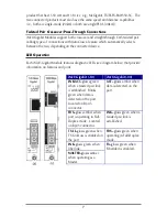
Page 10: ...iMcV Gigabit Module features diagnostic LEDs see diagram below that provide information on features and ports iMcV Gigabit 10 iMcV Gigabit 00 LNK ACT glows green when a twisted pair link is establishe...

Page 11: ...check the following o Solution 1 Within the switch configuration either via SNMP or a CLI ensure that the setting for the fiber port in use is set to 1000 Mbps Full Duplex Manually setting the switch...

Page 12: ...9 Notes...
Page 13: ...tworks com Web www imcnetworks com Specifications Environmental Operating Temperature 32 104 F 0 40 C Storage Temperature 0 160 F 20 70 C Humidity 5 95 non condensing Power Consumption Typical iMcV Gi...

Page 14: ...11 IMC Networks Technical Support Tel 949 465 3000 or 800 624 1070 in the U S and Canada 32 16 550880 Europe Fax 949 465 3020 E Mail techsupport imcnetworks com Web www imcnetworks com...

Page 15: ...ars this symbol on product or packaging must not be disposed of with unsorted municipal waste This symbol indicates that the equipment should be disposed of separately from regular household waste It...

Page 16: ...t notice IMC Networks assumes no responsibility for any errors that may appear in this document iMcV Gigabits a trademark of IMC Networks Other brands or product names may be trademarks and are the pr...

Reviews: