background image


12 | 

P a g e


WasteStation Compact 

INITIAL OPERATION 
 

1.


Switch on the electricity and water supplies. 


2.


Ensure that a waste bin is in place in the machine outlet area 

(a red light will illuminate if 

the bin is not in place)


3.


 Press the green 

‘START’

 button, water should flow immediately, if no water flows within 2 > 

3 seconds, press the emergency stop button to stop the machine and check the water supply 
connections and ensure that the water supplies are turned on.  
 

4.


With the machine running, inspect the waste and water supply piping for leaks. Use a flow 
meter  to  check  that  the  volume  of  water  flowing  is  correct  –  refer  to  WATER  SUPPLY 
CONNECTION. If adjustments are needed, use a screwdriver to adjust the position of the slot 
on the control screw of the service valve. Maximum flow is with the slot in line with the pipe. 
 

5.


Undo the front panel of the machine by releasing the black catch on the front panel. Ensure 
that  the  auger  within  the  dewaterer  (WastePro  II)  is  rotating  in  a  clockwise  direction 
(viewed from top and same direction as the arrow on the motor). Replace the front panel 
ensuring the catch is secured. 


6.


 Try  a  small  amount  of  food  waste  (see  poster  on  next  page)  to  check  disposal  and 
dewatering are working successfully and that there is no internal obstruction in the waste 
pipe causing a blockage. Also check that a small amount of waste goes into the waste bin. 
 

7.


With the machine running unscrew the baffle interlock knob .The machine will switch itself 
off almost immediately. By the time the knob is fully unscrewed and the safety baffle open, 
the rotor in the grinding chamber will have completely stopped. 
When these checks, tests and adjustments are completed, the IMC WasteStation 
Compact is ready for use. 


On completion of installation, Commissioning, the appliance is now operational. The person in 
charge of this equipment must keep this manual in a safe place and accessible to all operators and 
servicing providers. It is the site’s responsibility to ensure adequate training and instruction has 
been provided to all associated personnel involved in the operation of the appliance.  
If you are unsure about any part of this manual, contact 

service@imco.co.uk

 Tel: 01978 661155  


Summary of Contents for WasteStation Compact

Page 1: ...1 P a g e WasteStation Compact WasteStation Compact SINGLE PHASE MODEL 240V 50HZ F79 240 INSTALLATION AND OPERATING MANUAL PLEASE LEAVE WITH OPERATOR A34 101 R1 ECNs 8894 8854 January 2020 ...

Page 2: ... CONNECTION 8 ELECTRICAL CONNECTION 9 MACHINE RATINGS 10 TESTING 10 OPERATION OF MACHINE 11 MACHINE RUNNING MODES INDICATOR LIGHTS 11 INITIAL OPERATION 12 NORMAL OPERATION 14 RELEASING A JAM 14 NOTE 15 WATER FLOW CONTROL 15 ONGOING MACHINE REQUIREMENTS 15 USAGE 16 CIRCUIT DIAGRAM 17 PARTS LIST MACERATOR 18 EXPLODED VIEW 1 19 EXPLODED VIEW 2 20 EXPLODED VIEW 3 21 EXPLODED VIEW 4 22 PARTS LIST F79 2...

Page 3: ...3 P a g e WasteStation Compact MACHINE DIMENSIONS ...

Page 4: ...4 P a g e WasteStation Compact View on Rear of Machine Showing Connections for Services ...

Page 5: ...rst ON DELIVERY Please check the contents against the following list and notify both the Carrier and Supplier within three days if anything is missing or damaged Fully assembled WasteStation with following items loose Release key 1 off Feeding Pusher 1 off Waste bin 3 off Instruction Manual 1 off Operating Plaque 1 off wall mounted self adhesive GUARANTEE This machine is guaranteed by IMC for 2 Ye...

Page 6: ...supplier in the event of any queries Be sure to leave this Instruction Manual with the user after the installation of the machine is complete The machine is operated from the wall mounted control box SELECTION OF SITE Select the site of the WasteStation Compact with care so that it is convenient both for the major source of food waste and for access by machine operators The machine should be insta...

Page 7: ...hten all nuts and re check levels 3 Continue with SUPPLY CONNECTION INSTRUCTIONS SUPPLY CONNECTIONS HOT AND COLD WATER INLET SUPPLIES THE FOLLOWING ARE IMPORTANT INSTALLATION REQUIREMENTS The plumbing system is to be installed and used in accordance with the requirements of the Water Supply Water Fittings Regulations and Byelaws The purpose of these regulations is to protect your drinking water su...

Page 8: ...ive that the waste pipe from the WasteStation bypasses any existing in line grease trap or grease separator that may be present unless said trap or separator has been specified to suit the output of the WasteStation along with the existing equipment Should a grease trap or separator be used solely for the WasteStation it must be specified by the supplier to suit the output of the WasteStation If t...

Page 9: ...c Should this apply the electrician must alter the cable accordingly The WasteStation must be connected to a suitable 16 AMP Single phase isolator providing at least 3mm separation in all poles The mains supply cord cable colours and cable markings are shown in the table below Warning This appliance must be earthed If the supply cord becomes damaged it must be replaced by qualified electrician in ...

Page 10: ... of this document WARNING This machine must be earthed WARNING This machine must not be PAT tested under any circumstances It contains an inverter motor drive which can be damaged by the test and the test results will be invalid anyway This advice is in accordance with standard practice within the industry and is due to the inductive capacitive components used within the inverter If in doubt pleas...

Page 11: ...ing out MACHINE RUNNING MODES INDICATOR LIGHTS When the machine is running the button lights on the front of the machine will be constantly lit or flash the meaning of this is explained below Solid Green Flashing Green No Lights Machine Running Machine Stopping Machine Stopped No Warnings Flashing Blue Solid Red Flashing Red Machine in Cleaning Mode WARNING Bin Not Present WARNING Bin Full Machine...

Page 12: ... viewed from top and same direction as the arrow on the motor Replace the front panel ensuring the catch is secured 6 Try a small amount of food waste see poster on next page to check disposal and dewatering are working successfully and that there is no internal obstruction in the waste pipe causing a blockage Also check that a small amount of waste goes into the waste bin 7 With the machine runni...

Page 13: ...13 P a g e WasteStation Compact ...

Page 14: ...am under overload or if unsuitable materials are placed inside IMC machines are designed to withstand this and no damage will normally result as the machine will switch itself off It is necessary to clear the jam as follows 1 Switch off at the mains isolating switch 2 Remove the baffle by unscrewing the interlock knob and lifting off 3 Take out any bulk waste in the disposal chamber Rubber gloves ...

Page 15: ...r of bends in the drainage piping and the fall of the pipe A bucket of warm NOT HOT soapy water poured into the FWD s hopper at the end of each day will both clean the equipment and help disperse any residual solids in the piping ONGOING MACHINE REQUIREMENTS Daily Clean down thoroughly after use especially inside the hopper Unscrew the safety interlock knob and open the baffle to gain access inter...

Page 16: ...G AND INTRODUCING WASTE OF A SIMILAR NATURE 4 DO NOT FEED LARGE AMOUNTS ALL AT ONCE THIS WILL CAUSE BLOCKAGES 5 IF FEEDING LARGE QUANTITIES OF THE SAME FOOD ITEM i e RICE PASTA POTATOES ETC IT MUST BE FED SLOWLY ALLOWING EACH SMALL BATCH TO PASS THROUGH THE DEWATERER INTO THE BIN OR BLOCKAGES MAY OCCUR 6 IN NORMAL OPERATION THE MACHINE SHOULD ALWAYS BE STOPPED BY PRESSING THE RED BUTTON THE EMERGE...

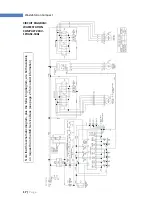
Page 17: ...tion Compact CIRCUIT DIAGRAM WASTESTATION COMPACT 240V 1PHASE 50Hz Note that this schematic diagram plus the full wiring diagram are both available on request from the IMC Service Desk see page 25 for contact information ...

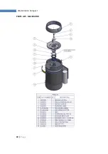
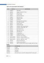
Page 18: ...18 P a g e WasteStation Compact PARTS LIST MACERATOR ...

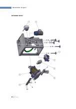
Page 19: ...19 P a g e WasteStation Compact EXPLODED VIEW 1 ...

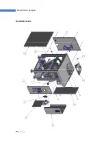
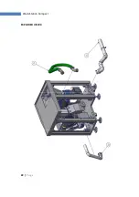
Page 20: ...20 P a g e WasteStation Compact EXPLODED VIEW 2 ...

Page 21: ...21 P a g e WasteStation Compact EXPLODED VIEW 3 ...

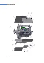
Page 22: ...22 P a g e WasteStation Compact EXPLODED VIEW 4 ...

Page 23: ...cket 14 S78 103 Dewaterer Complete Assy 1PH 15 S79 237 Start Stop Box Assy 16 S79 235 Macerator Assy 1PH 17 A19 034 Adjustable Foot 18 A09 034 Pump Full Assy 19 E79 269 Outlet Chute Clip On 20 E79 246 Dewaterer Lower Support 21 Fabricated Assy Pipe Assy Pump Dewaterer 22 Fabricated Assy Pipe Assy Dewaterer to Waste Drain 23 Fabricated Assy Pipe Assy Macerator Pump 24 S79 058 Bin Sensor Bracket Ass...

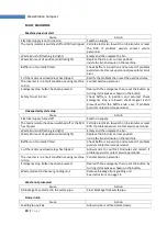
Page 24: ...hin the baffle knob assy If problem persists contact service personnel Unexpected system stop Cause Action Electrical supply turned off Switch on supply The mains isolator has been switched off or the RCD has tripped Call site electrician to switch on the isolator or reset RCD If problem persists contact service personnel Waste bin is full flashing red light Empty and then replace the bin Waste bi...

Page 25: ... spares and service support if applicable please call IMC on 44 0 1978 661155 Alternatively contact us via email or fax IMC Spares Desk Fax 44 0 1978 667759 E mail spares imco co uk IMC Service Desk Fax 44 0 1978 667766 E mail service imco co uk Imperial Machine Company Limited Unit 1 Abbey Road Wrexham Industrial Estate Wrexham LL13 9RF Tel 44 0 1978 661155 Fax 44 0 1978 729990 E mail info imco c...

Reviews: