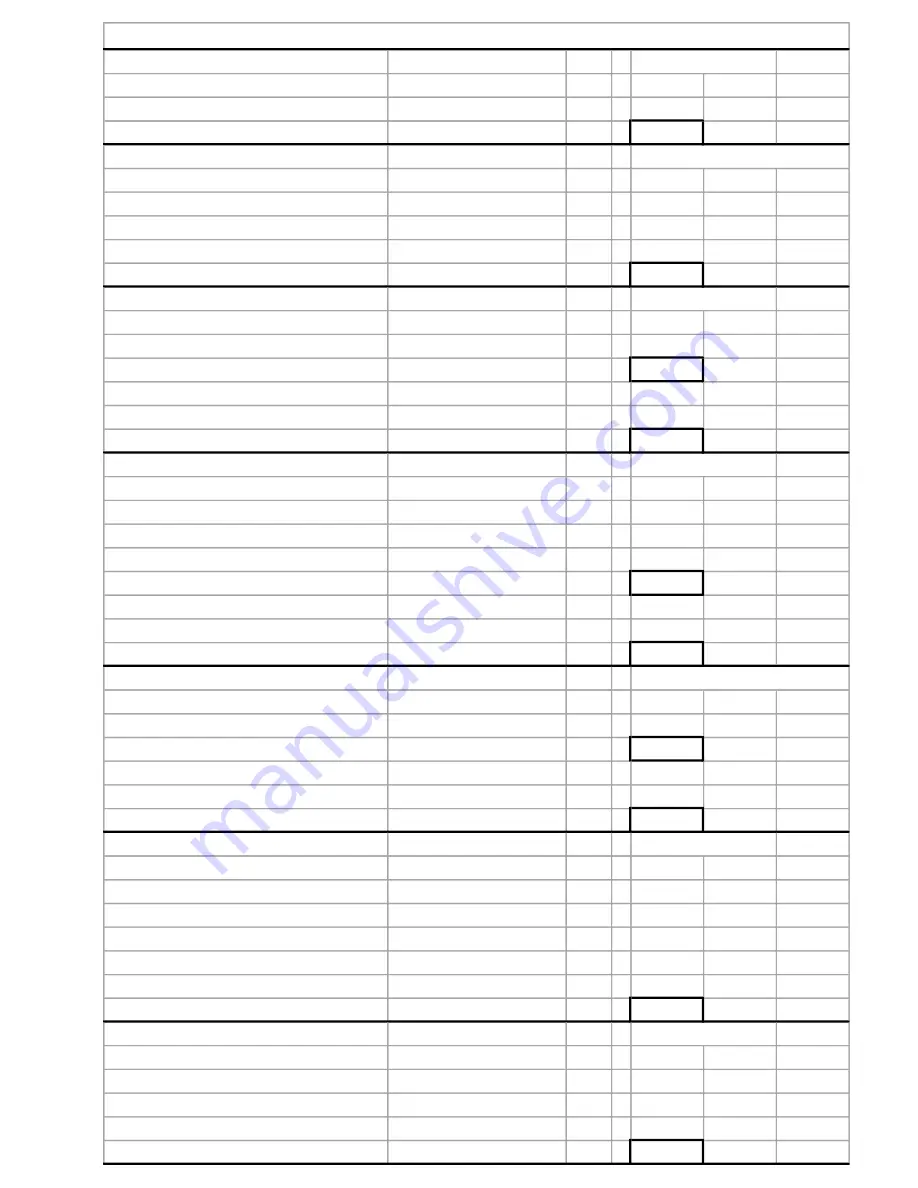
UPPER CAP
Parallels
2.250
Measurement
A
-
Norm
1.862
Cap Deck to Thrust Seat
Total
B
=
Norm
0.388
DECK TO PINION CENTERLINE
Deck to Tool
Measurement
C
Norm
2.252
Less Parallel
-
1.000
Total
Norm
1.252
Plus 1/2 tool
+
2.012
Deck to Pinion CL
Total
D
=
Norm
3.264
UPPER THRUST SEAT
Deck to Pinion CL
D
Norm
3.264
B
-
Norm
0.388
Pinion CL to Upper Thrust Seat
Total
E
=
Norm
2.876
Bearing Thickness
-
0.157
Mounting Distance
-
2.661
Race Thickness
F
=
Norm
0.060
LOWER THRUST SEAT
Measurement
G
Norm
7.138
Parallel
-
1.000
Deck to Lower Thrust Seat
Total
=
Norm
6.138
Deck to Pinion CL
D
-
Norm
3.262
Pinion CL to Lower Thrust Seat
Total
H
=
Norm
2.876
Bearing Thickness
-
0.157
Mounting Distance
-
2.661
Race Thickness
J
=
Norm
0.060
GEAR MEASURMENTS
Gear One
Measurement
K1
Norm
2.091
Less Parallel
-
1.000
Gear Depth One
Total
L
Norm
1.091
Gear Two
Measurement
K2
Norm
2.091
Less Parallel
1.000
Gear Depth Two
Total
M
=
Norm
1.091
GEAR ASSEMBLY
Gear Depth One
L
Norm
1.091
Gear Depth Two
M
+
Norm
1.091
Race Thickness
F
+
Norm
0.060
Race Thickness
J
+
Norm
0.060
2 x Bearing Thickness
+
0.314
Retainer Spacing
Measurement
N
+
Norm
3.162
Gear Assembly
Total
O
=
5.778
CAP CRUSH
Pinion CL to Upper Thrust Seat
E
+
Norm
2.876
Pinion CL to Lower Thrust Seat
H
+
Norm
2.876
Upper Thrust Seat to Lower Thrust Seat Total
P
=
Norm
5.752
Gear Assembly
Total
O
=
Norm
5.778
Cap Crush
=
Norm
.020-.030
SCX, SCX4 WORK SHEET Serial #
Page 9
Summary of Contents for Xtreme Advantage SCX
Page 6: ...Page 2 Upper Case Hardware Seals Fig 1...
Page 8: ...Upper Case Gear Components Fig 2 Page 4...
Page 12: ...Page 8 Page 8 SCX Setup Diagrams Fig 3...
Page 14: ...Backlash Assembly Fig 5 Page 10...
Page 16: ...Lower Gear Case Fig 6 Page 12...
Page 18: ...Lower Case Gear Fig 7 Page 14...
Page 20: ...Page 16 Lower Pinion Height Measurements Fig 8...
Page 23: ...Spline Seat Fig 9 Page 19...
Page 24: ...Running Load Page 20...


