background image

3

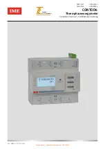
CONTO D6 

Three-phase energy meter

Installation manual

 • 

Installationsanweisungen

  Contents

Dangers and warnings   

4

Preliminary operations  

5

Presentation  

6

Installation 

7

Programming 

10

Use  

19

Assistanance  

22

Communication 

23

Technical characteristics 

27

List of abbreviation 

33

Summary

Gefahren und Warnungen  

4

Vorarbeiten   

5

Presentation   

6

Installieren 

7

Programmierung 

10

Verwendung   

19

Unterstützung 

22

Kommunikation 

24

Technische  Daten 

31

Liste der Abkürzungen 

34

• Dangers and warnings

This equipment must only be mounted by professionals.

The manufacturer shall not be held responsible for failure to comply with the instructions in this manual.

Risk of electrocution, burns or explosion

• The device must only be installed and serviced by qualified personnel.

• Prior to any work on or in the device, isolate the voltage inputs, short-circuit the secondary winding of each  current transformer and 

exclude the device auxiliary power supply.

• Always use an appropriate voltage detection device to confirm the absence of voltage.

• Put all mechanisms, door and covers back in place before energising the device.

• Always supply the device with the indicated rated voltage.

Failure to take these precautions could cause serious injuries.

Risk of damaging the device

Chek the following:

• The voltage to the voltage-input terminals, (U1, U2, U3 and N) according to the  values indicated in 

   the "Technical characteristics" section. 

• The network frequency (50 / 60 Hz).

• Gefahren und Warnungen


Diese Geräte dürfen nur von Fachleuten montiert werden.

Die Nichtbeachtung der vorliegenden Anweisungen entbindet den Hersteller von jeglicher Haftung.

Stromschlag-, Verbrennungs-und Explosionsgefahr

• Die Installation und Wartung dürfen nur von qualifizierten Fachleuten vorgenommen werden.

• Vor jedem Eingriff in das Gerät sind die Spannungseingänge auszuschließen, der Sekundärkreis jedes Stromwandlers zu 

kurzschließen und die Hilfsspannungsversorgung des Gerätes auszuschließen.

• Verwenden Sie immer ein geeignetes Spannungsmessgerät, um die Spannungsfreiheit zu überprüfen.

• Alle Geräte, Türen und Abdeckungen wieder montieren, bevor Sie das Gerät unter Spannung setzen.

• Verwenden Sie immer die angegebene Nennspannung, um das Gerät mit Strom zu versorgen.

Die Nichtbeachtung dieser Vorsichtsmaßnahmen kann zu schweren Verletzungen führen.

Beschädigungsgefahr des Gerätes

Bitte beachten:

• 

Eine Spannung an den Klemmen der Spannungseingänge (U1, U2, U3 und N) entsprechend den im Kapitel "Technische Daten" 

   angegebenen Werten.

•  Netzfrequenz 50/60 Hz

Tomek GmbH - messtechnik@tomek.at - 01/61003-0

Summary of Contents for CE6DMID52

Page 1: ...LE11068AA 07 18 03 IM CONTOD6 Three phaseenergymeter Installation manual Installationsanweisung CE6DT1252 CE6DT1256 CE6DMID52 CE6DMID56 Tomek GmbH messtechnik tomek at 01 61003 0 ...

Page 2: ...2 2 Tomek GmbH messtechnik tomek at 01 61003 0 ...

Page 3: ...e to take these precautions could cause serious injuries Risk of damaging the device Chek the following The voltage to the voltage input terminals U1 U2 U3 and N according to the values indicated in the Technical characteristics section The network frequency 50 60 Hz Gefahren und Warnungen Diese Geräte dürfen nur von Fachleuten montiert werden Die Nichtbeachtung der vorliegenden Anweisungen entbin...

Page 4: ...E6DMID56 4 Metrological LED 5 Key pad with 3 dual function keys display or configuration 6 LCD display 7 Consult the instruction manual before installation 8 Double insulation 9 Connectionon 3 phase 4 wire line 10 Anti rotation device 11 Voltage Current 12 Frequency 13 Product code 14 Double tariff 15 Outputs 16 Working temperature 17 Accuracy class 18 Year of approval 19 Certifying board 20 Certi...

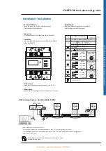
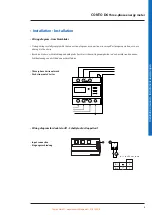
Page 5: ... x 50 mm COMBI PZ2 N MAX 2 1 x 1 mm 8 mm 2 1 x 1 mm 2 1 x 1 5 mm 0 5 x 2 5mm E RS485 5 C 55 C L1 L2 L3 B EN 50470 1 3 CE6DT125 CE6DMID5 5 Wh imp LED L1 3 L2 6 L3 9 L1 1 N 11 L2 4 L3 7 Auxiliary supply derived from the voltage terminals terminals U1 U2 U3 N Hilfsversorgung abgeleitet von den Spannungsanschlüssen Klemmen U1 U2 U3 N IF4E011 SXIIP CE6DT1256 CE6DMID56 CE6DT1256 CE6DMID56 CE6DT1256 CE6D...

Page 6: ...with the connection diagram a connection error may affect proper operation or cause damage to the device Beachten Sie bei der Verdrahtung unbedingt das Anschlussschema Ungenauigkeiten in den Anschlüssen können zu Fehlbedienungen oder Schäden am Gerät führen Wiring diagram for double tariff Schaltplan für Doppeltarif 1 C SG E 1 C V 12 24 VDC max 10 mA 1 1 E 1 C 1 i i V Tar 1 0 1 Tar 2 Input connect...

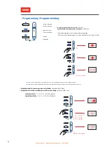
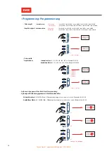
Page 7: ...ter 1 minute of inactivity on the keyboard the device exits the programming mode without saving the changes Anmerkung Nach 1 Minute Inaktivität der Tastatur beendet das Gerät die Programmierphase ohne die Änderungen zu speichern Programming Programmierung Selectable values 5 8 10 15 20 30 60 minutes Anwählbare Werte 5 8 10 15 20 30 60 Minuten Integrationtime for average power calculation Example t...

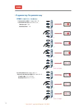
Page 8: ...alues 1 255 Anwählbare Werte 1 255 x 1 confirm bestätigen E P Q S I U OK 3 SET x 1 x 2 RS485 CE6DT1256 CE6DMID56 E P Q S I U OK 3 SET E P Q S I U OK 3 SET x 1 confirm bestätigen E P Q S I U OK 3 SET k k k x 1 Communication speed Example bAUd 9 6 Kommunikationsgeschwindigkeit Beispiel bAUd 9 6 Selectable values 4 8 9 6 19 2 bit s Anwählbare Werte 4 8 9 6 19 2 bit s Tomek GmbH messtechnik tomek at 0...

Page 9: ...onfirm E P Q S I U OK 3 SET Parity bit Example PAR odd Paritätsbit Beispiel PAR odd Selectable values EVEn odd nonE Anwählbare Werte EVEn odd nonE E P Q S I U OK 3 SET E P Q S I U OK 3 SET x 1 nonE X 2 odd RS485 CE6DT1256 CE6DMID56 Tomek GmbH messtechnik tomek at 01 61003 0 ...

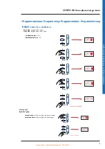
Page 10: ...I U OK 3 SET E P Q S I U OK 3 SET x 5 E P Q S I U OK 3 SET Selectable values 3 99 Anwählbare Werte 3 99 x 1 confirm bestätigen E P Q S I U OK 3 SET x 1 x 1 RS485 CE6DT1256 CE6DMID56 Selectable values ACt active energy rEA reactive energy Anwählbare Werte ACt Wirkenergie rEA Blindenergie Pulse output Impulsausgang x 1 E P Q S I U OK 3 SET x 1 confirm bestätigen E P Q S I U OK 3 SET Tomek GmbH messt...

Page 11: ...le values 50 100 200 300 400 500 ms Example PLSd 100 Anwählbare Werte 50 100 200 300 400 500 ms Beispiel PLSd 100 Pulse width Impulsdauer x 1 100 ms x 2 200 ms x 3 300 ms x 4 400 ms x 5 500 ms E P Q S I U OK 3 SET x 1 confirm bestätigen E P Q S I U OK 3 SET Selectable values 0 4 50 Pn Pn 3 Phase active energy referred to 400V 10A 6900W Example thr 02 40 Anwählbare Werte 0 4 50 Pn Pn Wirkenergie 3 ...

Page 12: ... new password and store it in a secur e place Important The last password saved must be used for future access Wichtig Um zu einem späteren Zeitpunkt auf das System zugreifen zu können ist das zuletzt gespeicherte Kennwort erforderlich Bitte notieren Sie sich das neue Kennwort und bewahren Sie es an einem sicheren Ort auf Saving settings Instellungen speichern Tomek GmbH messtechnik tomek at 01 61...

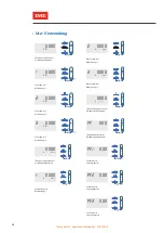
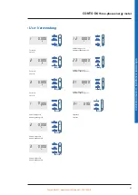
Page 13: ...rgie XXXXXXXX P k Wh E E E P Q S I U OK 3 SET Average active power demand tariff 1 Durchschnittswirkleistungsspitzenwert im Tarif 1 XXXX P M D k W E P Q S I U OK 3 SET Average active power demand tariff 2 Wirkleistungsspitzenwert im Durchschnitt Tarif 2 XXXX P M D k W E P Q S I U OK 3 SET Partial reactive energy Teilblindenergie XXXXXXXX P k v a r h P Q S I U OK 3 SET Average power Leistungsmittel...

Page 14: ...S I U OK 3 SET Three phase power factor Dreiphasenleistungsfaktor PF XXX E P Q S I U OK 3 SET P Q S I U OK 3 SET E P Q S I U OK 3 SET E P Q S I U OK 3 SET Active power L3 Wirkleistung L3 Three phase reactive power Dreiphasenblindleistung XXXX k v a r Reactive power L1 Blindleistung L1 XXXX k v a r Reactive power L2 Blindleistung L2 2 XXXX k v a r Reactive power L3 Blindleistung L3 3 XXXX k v a r P...

Page 15: ...rom L3 2 XXXX V E P Q S I U OK 3 SET 3 XXXX V E P Q S I U OK 3 SET Phase voltage L1 N Phasenspannung L1 N XXXX V P Q S I U OK 3 SET E Phase voltage L2 N Phasenspannung L2 N Phase voltage L3 N Phasenspannung L3 N 23 XXXX V E P Q S I U OK 3 SET 3 XXXX V E P Q S I U OK 3 SET Linked voltage L1 L2 Verkettete Spannung L1 L2 2 XXXX V P Q S I U OK 3 SET E Linked voltage L2 L3 Verkettete Spannung L2 L3 Lin...

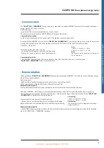
Page 16: ...2 bits Nota The response time question answer time out is 200 ms maximum Kommunikation Die Energiezähler CE6DT1256 CE6DMID56 kommunizieren über das MODBUS Protokoll was einen Dialog nach einer Master Slave Logik impliziert Adressierungsart Punkt zu Punkt der Master kommuniziert mit jeweils nur einem Slave Gerät Die Kommunikation erfolgt im RTU Modus Remote Terminal Unit Kommunikationssyntax Die St...

Page 17: ...ement Imin 0 5A Itr 1A Ib 10A CE6DT1252 CE6DT1256 Iref 10A CE6DMID52 CE6DMID56 Imax 125A Current circuit power consumption Max 2 5W per phase Short time overcurrent IEC EN 62053 21 IEC EN 62053 23 30 Imax 10ms Frequency Code CE6DT1252 CE6DT1256 47 63 Hz Code CE6DMID52 CE6DMID56 49 51 Hz 59 61Hz Energies Code CE6DT1252 CE6DT1256 Active energy accuracy class 1 IEC EN 62053 21 Reactive energy accurac...

Page 18: ...with The requirements of the European directe on electromagnetic compatibility EMC n 2014 30 EU The low voltage directive n 2014 35 UE Directive 2011 65 EU modified by directive 2015 863 RoHS 2 Electromagnetic compatibility According to IEC EN 62052 11 EN 50470 1 Insulation IEC EN 62052 11 IEC EN 62053 21 Measurement category III Degree of pollution 2 Insulation voltage Ui 300V Phase Earth Impulse...

Page 19: ...1A Ib 10A CE6DT1252 CE6DT1256 Iref 10A CE6DMID52 CE6DMID56 Imax 125A Selbstverbrauch Stromkreis Max 2 5W pro Phase Kurzzeitige Überlastung IEC EN 62053 21 IEC EN 62053 23 30 Imax 10ms Frequenz Code CE6DT1252 CE6DT1256 47 63 Hz Code CE6DMID52 CE6DMID56 49 51 Hz 59 61Hz Energie Code CE6DT1252 CE6DT1256 Genauigkeitsklasse Wirkenergie 1 IEC EN 62053 21 Genauigkeitsklasse Blindenergie 2 IEC EN 62053 23...

Page 20: ...hen Den Bestimmungen der Europäischen Richtlinie über die elektromagnetische Verträglichkeit EMV Nr 2014 30 EU Der Niederspannungsrichtlinie 2014 35 EU Der Richtlinie 2011 65 EG geändert durch Richtlinie 2015 863 RoHS 2 Elektromagnetische Verträglichkeit Prüfungen gemäß IEC EN 62052 11 EN 50470 1 Isolation IEC EN 62052 11 IEC EN 62053 21 Messkategorie III Verschmutzungsgrad 2 Isolationsspannung Ui...

Page 21: ...ting Tariff 2 PF Power factor Fr Frequency Itr Transitional current Iref Reference current 10Itr Liste der Abkürzungen CodE Zugriffscode tIME Integrationszeit Leistungen Addr Adresse bAUd Kommunikationsgeschwindigkeit in kbps PAr Parität nonE Parität keine EVEn Parität Gleich odd Parität Ungerade tIM Antwortverzögerung ms PLSt Einstellung Impulsausgang ACt Wirkenergie kWh rEA Blindenergie kvarh PL...

Reviews: