background image

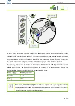
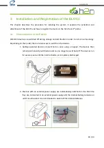
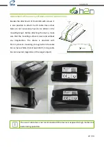
The   device   is   not   powered   while   shipped   to   avoid   radio   transmissions   during   shipping   and
especially on airplanes. To enable the device simply hold a magnet over the device label and the
device will be activated and stay activated for the whole lifetime.

Timing Specifications

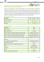
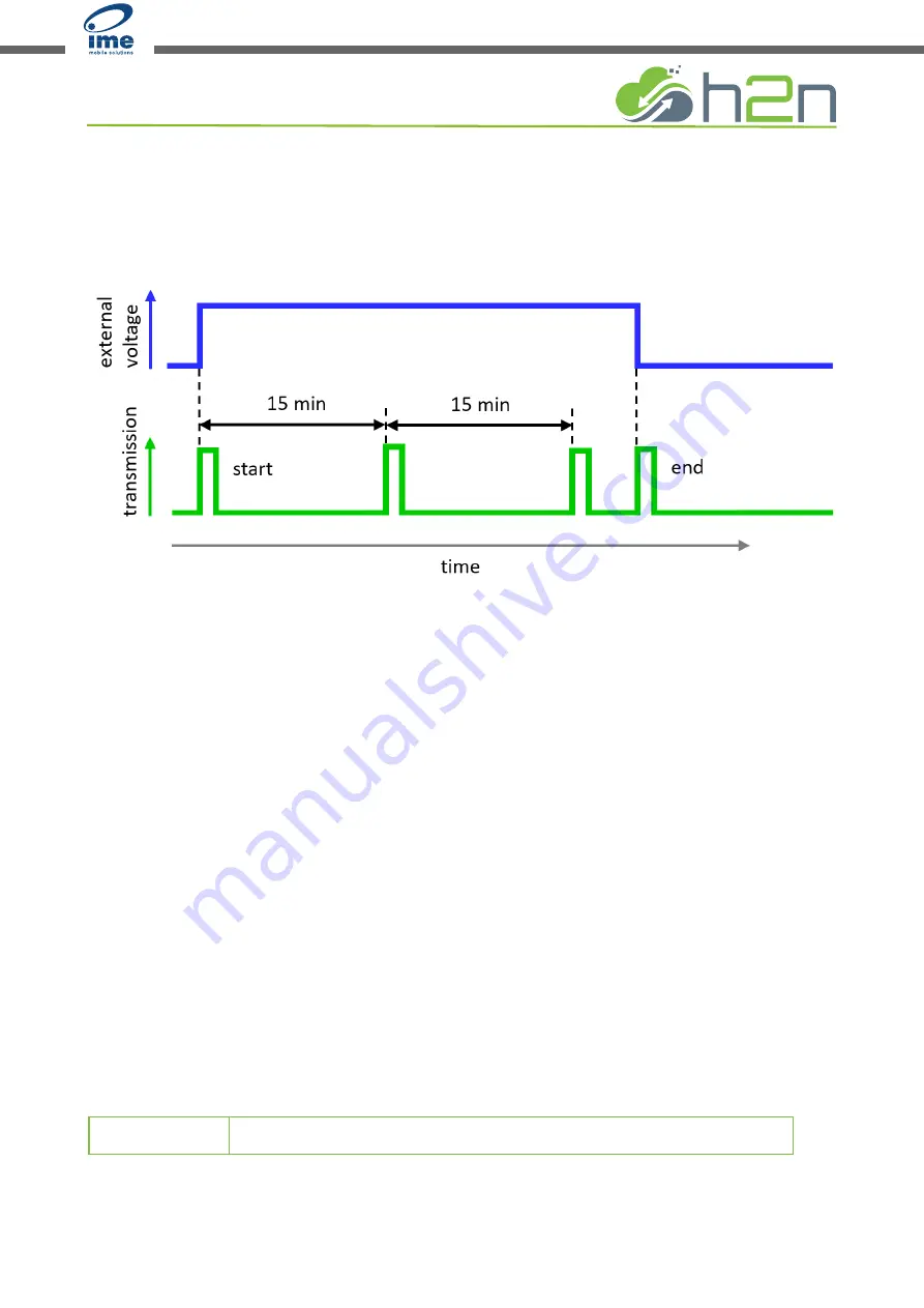
External supply is detected when the voltage is minimum 8 volts. The device will start sending its

first data packet immediately after external voltage is supplied and will then send periodic data
packets with a default timing of 15 minutes. When the external supply is removed, a special end of

external supply packed is sent to ensure that the last position of the device is captured. All setup
configurations can be changed once per day when the device checks for a configuration change

with a special protocol packet. While operating under external supply, the device will send position
data   every   15 minutes   and   external   input   voltages   and   operating   hours   approximately   every

45 minutes. While not in external supply mode, the device will be controlled by an internal timer
which will turn the device on every 2 hours and will check configurations to send keep alive

messages every 6 hours. The behavior is set by default to transmit Temperature, Operating hours
and Battery voltage every 3 times which equals to 6 hours. Once per Day the device will also send

its location data and request a new configuration from the Cloud server. Timing of these messages
can also be changed with the cloud configuration. Operating hours are sent every 15 minutes when

external supply is present and at when external supply is removed.

operating mode

15 / 33

www.ime.de

Summary of Contents for Home2Net ELOC3

Page 1: ...Home2Net User Manual EL3VT2 www ime de...

Page 2: ...es 13 Functional Description Specifications 14 2 4 h2n Track it 17 3 Installation and Registration of the ELOC3 18 3 1 First Activation of the ELOC3 18 3 2 Attachment of the ELOC3 19 Attachment with s...

Page 3: ...compilation of illustrations and texts Nevertheless errors cannot be excluded The compilation is made without guarantee Home2Net GmbH All rights including photomechanical rights reserved Rendition and...

Page 4: ...well as high temperature fluctuations Please read this manual carefully for proper installation and handling of the device Incorrect installation may cause a danger to the user or third parties In ad...

Page 5: ...es as an end user You may return batteries free of charge after use to the Seller or to the designated collection points e g municipal collection points or retailers The crossed out dustbin symbol mea...

Page 6: ...is declaration of conformity is issued under the sole responsibility of the manufacturer The certificate is issued after testing of the named product s and or audit of the technical documentation and...

Page 7: ...of the areas covered can be found at https www sigfox com en coverage If there is no Sigfox network in your region you can contact Sigfox at https www sigfox com en coverage become so to become a Sigf...

Page 8: ...and M_001A_E56F_01 SIGFOX REFERENCE BUIL 453 SIGFOX FEATURES DOWNLINK PAYLOAD ENCRYPTED MONARCH QF_585 Sigfox Ready Certificate P_013F_CD8E_01 Congratulations home2net GmbH the following product is n...

Page 9: ...g conditions without getting damaged or being unusable 1 6 About this manual Read this manual carefully It contains important information about the installation and operation of the ELOC3 Pay particul...

Page 10: ...gurable operating modes In the sensor monitor version external signals and sensors can also be integrated The internal sensors detect I acceleration II shock III temperature IV illumination and V tilt...

Page 11: ...h2n Track it cloud The accuracy with which the position of the device is determined via GPS depends on the power supply of the device The ELOC3 can be powered by a battery or an external power supply...

Page 12: ...1 Container Tracker EL3ET1 Equipment Tracker EL3IS1 Impact Sensor EL3VT2 Vehicle Tracker Depending on the type there are two different versions with regard to power supply and sensor technology The de...

Page 13: ...ensors for orientation rotation and temperature Ultra low power motion sensor to activate the device with fully automatic motion detection Hardware timer to activate the device for periodic radio mess...

Page 14: ...Cloud once every 28 hours Absolute maximum ratings Description Min Max Unit Storage Temperature 40 70 C Maximum Shock 200 g Humidity 5 100 Operational ratings Description Value Sigfox radio zone RZ1 R...

Page 15: ...when the device checks for a configuration change with a special protocol packet While operating under external supply the device will send position data every 15 minutes and external input voltages a...

Page 16: ...n detected End of Motion configuration Timing 24h 1 30 min 1 Every 28h Temperature Every 28h Battery voltage Every 28h Orientation 24h 1 30 min 1 yes Rotation 24h 1 30 min 1 yes 1 configurable by user...

Page 17: ...y looking at a the device icons on the map Tracking and logging of historic data make h2n Track it a comprehensive solution for many industries and use cases For more instructions please see the chapt...

Page 18: ...ending on the model there are two ways to switch on the devices 1 battery operated devices are switched on once using a magnet The devices then remain permanently switched on and can no longer be swit...

Page 19: ...oving parts it is advisable to mount them indoors as long as the GPS availability is sufficient Please pay particular attention to Chapter 3 4 For the application on moving parts with high mechanical...

Page 20: ...Drill two 4 5 mm holes in the mounting target at a distance of 92 mm Be sure to maintain the distance accurately to avoid mechanical damage when attaching Also make sure that the drilled holes are cle...

Page 21: ...ng surface is clean and without any irregularities Remove burrs and sharp edges to avoid damaging the insulation of the cables When installing the unit follow the instructions and notes in the previou...

Page 22: ...target Before attaching the device make sure that the mounting surface is clean and without any irregularities The device is provided with 55 mm joints for mounting through which the cable tie can be...

Page 23: ...t of the device to vehicles participating in road traffic should only take place indoors or should be protected in such a way that no other road user can be affected if the device falls off the vehicl...

Page 24: ...the devices in the field can not be taken over by other users For OEM s devices can also be pre registered by h2n The initial location setup can be used to give the device a proper location or specify...

Page 25: ...lly created a new account You can now login to use the h2n Track it Cloud application Register a Device to your Account To register a new Device to your account proceed as follows 1 login to the websi...

Page 26: ...he Device If you are not able to add the device please validate your input If still no registration is possible click on the Cannot register device button The support team will then be informed and wi...

Page 27: ...e set individually 1 2 3 4 6 12 times day H Threshold level that triggers motion mode If this value is exceeded a movement is registered Please keep in mind that an increased transmission frequency wi...

Page 28: ...e mounted properly The devices should not be covered by sheets of metal which would interfere with the functionality and connectivity of the device Please do not place the device next to a magnet to a...

Page 29: ...tallation instructions please refer to Chapter 3 4 1 Main Screen Devices can be tracked on scalable maps in street view or satellite view for the actual day or any user specified time range To use the...

Page 30: ...oad the Map I Enter the Device Management J Enter the Settings K Enter the Frequently Asked Questions FAQs L See your profile you are logged in with Here you can logout M Change the Map View N Click t...

Page 31: ...ttings for each Device can be setup Enter the Device Settings Name Comment Tag Timer Mode Frequency Sensor Settings Enter the Notification Settings Edit add geo fences Share or transfer the Device You...

Page 32: ...hen the geo fence shall be active D Select the time when the geo fence shall be active E Enter your Email address Click on TEST to receive a test message F Define the geo fence It is possible to defin...

Page 33: ...4 4 Sensor data display A graphical user interface shows the status and historical data by a simple click on any device icon on the map 33 33 www ime de...

Reviews: