background image

10781405W

LOAD

S1

P1

X

2 5 8 11

1

4

7

3

12 13

OUTPUT

I N P U T

RS 485


     Rx / Tx  GND   

33 34 35

+ –

20

AUX.

SUPPLY

21

VOLTAGE

CURRENT

L

N

a

A

b

B

2

11

F

S1

P1

S1

P1

LOAD

2 5 8 11 1

4

7

3

12 13

OUTPUT

I N P U T

RS 485


     Rx / Tx  GND   

33 34 35

+ –

20

AUX.

SUPPLY

21

VOLTAGE

CURRENT

2

5

8

F

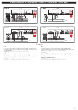
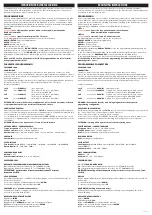
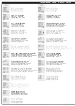
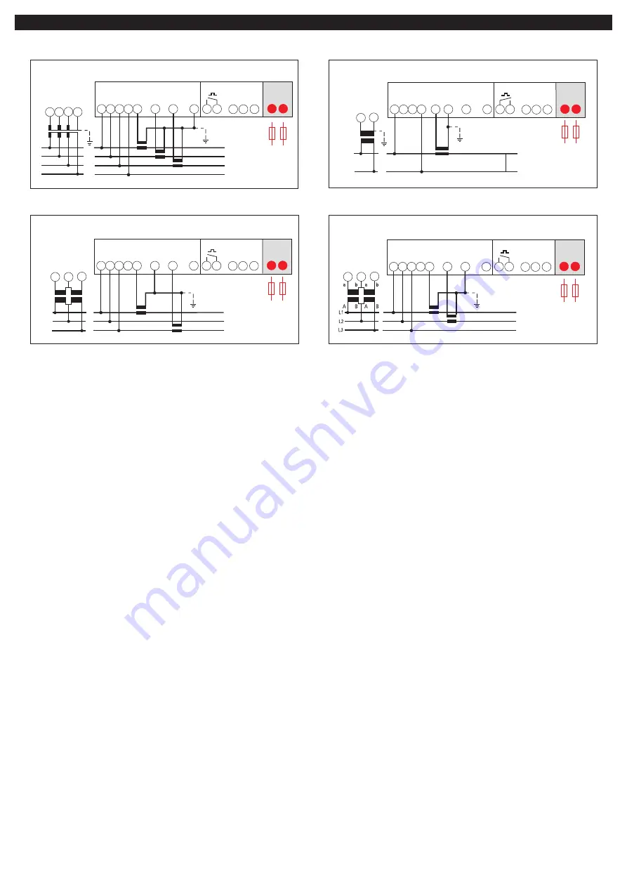
SCHEMI D’INSERZIONE • WIRING DIAGRAMS • SCHEMAS DE RACCORDEMENT • ANSCHLUßBILD

S1

P1

S1

P1

S1

P1

LOAD

2 5 8 11 1

4

7

3

12 13

OUTPUT

I N P U T

RS 485


     Rx / Tx  GND   

33 34 35

+ –

20

AUX.

SUPPLY

21

VOLTAGE

CURRENT

a

A

L1

L2

L3

N

2

11

5 8

F

S1

P1

S1

P1

LOAD

2 5 8 11 1

4

7

3

12 13

OUTPUT

I N P U T

RS 485


     Rx / Tx  GND   

33 34 35

+ –

20

AUX.

SUPPLY

21

VOLTAGE

CURRENT

a

A

b

B

a

A

b

B

L1

L2

L3

2

5

8

F

S 1000/164

S 1000/251

S 1000/167

S 1000/166

NOTA

Negli schemi sono sempre indicate le configurazioni con uscita impulsi e comunicazione RS485.
Nelle versioni che non prevedono uscita impulsi o comunicazione RS485 non si deve tenere conto
dei relativi collegamenti.

ATTENZIONE! collegare alimentazione ausiliaria ai terminali 20 e 21

NOTE

Sur les schèmas sont toujours indiquèes les configurations avoc sortie à impulsions et communica-
tion RS485. Pour les versions sans sortie à impulsions ou communication RS485, on ne doit pas
tenir compte des connexions relatives.

ATTENTION! raccorder l’alimentation auxiliaire sur le bornes 20 et 21

NOTE

The wiring diagrams, show the device complete with pulse output and RS485 interface.
In case of version without of these features, the corresponding terminals must not be considered.

WARNING! auxiliary supply must be connected to terminals 20 and 21

ANMERKUNG

Auf den Schaltbilder sind immer die Konfigurationen mit Impulsausgang und Kommunikation
RS485 angegeben. Für die Modelle ohne Impulsausgang und Kommunikation RS485, muß man
nicht die 
dazugehörige Verbindungen aufzeichnen.

ACHTUNG! hilfsspannung (aux.supply) anscließen klemmen 20und 21

3-2E

3n3E

3-2E

1n1E

: 0,5A gG

Summary of Contents for nemo 72-l

Page 1: ...10781405W Via Travaglia 7 20094 CORSICO MI ITALY Tel 39 02 44 878 1 www imeitaly com info imeitaly com ISTRUMENTI MISURE ELETTRICHE SpA I Cod MF7F MF9F 07 13 Nemo 72 L 96 L 10781405W...

Page 2: ...a impulsi o comunicazione RS485 non si deve tenere conto dei relativi collegamenti ATTENZIONE collegare alimentazione ausiliaria ai terminali 20 e 21 NOTE Sur les sch mas sont toujours indiqu es les c...

Page 3: ...a fase L1 REGOLAZIONE CONTRASTO DISPLAY 1 Premere ENTER 2 Sul display appare 8 8 8 8 3 Agire sui tasti UP DOWN per regolare il contrasto del display 4 Ottenuta la regolazione desiderata premere ENTER...

Page 4: ...L appareil ne n cessite pas de soins particuliers pour son installation m canique et lectrique Avant de proc der l installation il faut v rifier que les donn es indiqu es sur la plaque tension courant...

Page 5: ...Blindenergie Corrente di fase Energia attiva Phase current Active energy Courant de phase Energie active Phasenstrom Wirkenergie Frequenza fattore di potenza energia reattiva Frequency power factor r...

Page 6: ...N Re Tempo integrazione Time period Temps d int gration Integrationszeit Potenza Power Puissance Leistung Potenza media Power max demand Puissance moyenne Mittlere Leistung Corrente media Current max...

Page 7: ...Adresse 1 255 Adresse 1 255 COMUNICAZIONE RS485 RS485 COMMUNICATION COMMUNICATION RS485 KOMMUNIKATION RS485 Velocit comunicazione Baud rate Vitesse de communication Kommunikationsgeschwindigkeit USCI...

Page 8: ...6Kbit s 19 2Kbit s 001 001 001 002 003 004 005 1imp 0 01kWh 1imp 0 1kWh 1imp kWh 1imp 10kWh 50ms 100ms 200ms 300ms 0001 0001 0001 0002 0003 0004 01 0 01 0 01 1 01 2 01 3 1imp 100kWh 0000 1000 2000 20...

Reviews: