background image

40

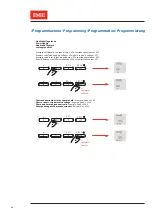
• Funzione di prova dei collegamenti • Connection test function              

• Fonction de test du raccordement • Verbindungstestfunktion

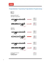
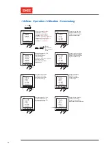
 Achèvement de la procédure

 Completion of the procedure

 Completamento della procedura


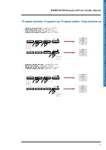
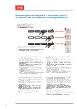
Afin d'obtenir des mesures correctes, le dispositif a 

s choix suivants:  


1. La tension à la borne V1 est connectée aux bornes de 

  courant S1 et S2 de I2 


2. La tension sur la borne V3 est reliée aux bornes de  

  courant S2-S1 de I1, et le même courant est inversé     

  de 180° 


3. La tension à la borneV2 est connectée aux bornes de  

  courant S1-S2 de I3 


Se Si l'utilisateur a choisi “SAVE no”, il doit faire ce qui suit: 

1. Échangez les  s aux bornes S1-S2 de I2 et S2-S1 de I1  

  en inversant ces derniers  


2. Échangez les câbles aux bornes V3 et V2 


3. 

d'usine (mot de passe 5555) 

4. Pour la sécurité relancer la procédure de test


To obtain correct measurements, the device has made:  

1. The voltage at terminal V1 is connected to the current 

The voltage at terminal V3 is connected to the current 

  terminals S1 and S2 of I2   


2. 

  terminals S1 and S2 of I1 and the current itself is 

  reversed by180°  


3. Voltage at terminal V2 is connected to the current  

  terminals S1 and S2 of I3   


If the user has chosen “SAVE no”   proceed as follows: 

1. Swap the wires to terminals S1-S2 of I2 and S2-S1 

  of I1 reversing the latter   


2. S

Enter

wap the cables to terminals V3 and V2


3. 

factory co

ration (password 5555) 

4. For safety relaunch the test procedure

• 

Um die korrekten Messungen zu erhalten, hat das Gerät 

die folgenden Einstellungen vorgenommen:

1. Die Spannung an der Klemme V1 ist an den Strom 

     über die Klemmen S1-S2 von I2 angeschlossen worden 

2. Die Spannung an der Klemme V3 ist an den Strom 

 über die Klemmen S1-S2 von I2 angeschlossen worden 

 und der Strom selbst ist um 180° verdreht. 


3. Die Spannung an der Klemme V2 ist an den Strom 

     über die Klemmen S1-S2 von I3 angeschlossen worden 


   Wenn der Benutzer "SAVE no" gewählt hat, muss er wie 

folgt vorgehen:

1. Vertauschen Sie die Kabel an den Klemmen 

S1-S2 von I1 und S2-S1 von I2


2. Vertauschen Sie die Kabel an den Klemmen V3 und V2.

   3.  Geben Sie die werkseitige Konfiguration ein (Passwort 5555)

4. Sicherheitshalber, die Selbstdiagnose neu starten


Per ottenere delle misure corrette, il dispositivo ha 

eseguito le seguenti scelte : 


1. La tensione al morsetto V1 è stata collegata alla  

  corrente ai morsetti S1-S2 di I2 


2. La tensione al morsetto V3 è stata collegata alla  

  corrente ai morsetti S1-S2 di I1  e la corrente stessa è  

  invertita di 180° 


3. La tensione al morsetto V2 è stata collegata alla  

  corrente ai morsetti S1-S2 di I3 


   Se l’utilizzatore ha scelto “SAVE no” dovrà procedere 

nel modo seguente: 


1. Scambiare i cavi ai terminali S1-S2 di I1 ed S2-S1 di I2  

  invertendo quest’ultimi    


2. Scambiare i cavi ai terminali V3 e V2. 

   3. Inserire la c

razione di fabbrica (password 5555) 

4. Per sicurezza rilanciare l’autodiagnostica


• 

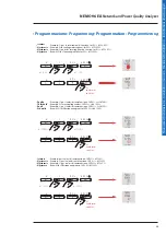
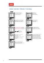
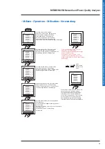
Déplacement des courants dans les positions correctes

 Shifting currents in the correct locations

Die Ströme in die richtigen Positionen bringen

• 

Spostamento delle correnti nelle posizioni corrette

I

U

P  Q  S

E  PF  F

x 1

I

U

P  Q  S

E  PF  F

I

U

P  Q  S

E  PF  F

 Vervollständigung des Verfahrens

x1

conferma /

Summary of Contents for NEMO 96 EA MFQ96021

Page 1: ...10783770WEB 11 17 01 IM NEMO96EA NetworkandPowerQualityAnalyzer Manuale d installazione Installation manual Manuel d installation Installationsanweisungen MFQ96021 MFQ96022...

Page 2: ...2 2...

Page 3: ...tion 6 Installation 7 Connection 8 Accessory modules 11 Programming 13 Operation 31 Connection test function 37 Assistance 42 Technical features 43 Glossary of abbreviations 63 Sommaire Danger et aver...

Page 4: ...m current of 1 2 A CT x 1 A or 6 A CT x 5 A on the current input terminals I1 I2 and I3 Danger et avertissement Le montage de ce produit ne peut tre effectu que par des professionnels Le non respect d...

Page 5: ...the product has not been damaged during transport the product reference number conforms to your order the package contains the item and operating instructions Op rations pr alables Pour la s curit du...

Page 6: ...klit LCD display 4 Values 5 Phase 6 Measurement unit 7 Hour meter and energy display Pr sentation 1 Clavier 4 touches pour visualiser l ensemble des mesures et modifier les param tres de configuration...

Page 7: ...commendations Avoid proximity to systems which generate electromagnetic interference Dima di foratura Cut out diagram Plan de d coupe Bohrschablone Montaggio Mounting Montage Montage Recommandations v...

Page 8: ...Hz 110 300 V d c MFQ96022 Aux 11 60 V d c F 1 A gG Installazione Installation Installation Installieren 3N 3E 3N 3E U U U U U U U U U U U U 5 2 8 11 21 20 5 2 8 11 21 20 3 3E U U U U U U 5 2 8 11 21 2...

Page 9: ...installation Installationsanweisungen Installazione Installation Installation Installieren 3 1E 3N1E U U U U U U U U U U U U 5 2 8 11 21 20 5 2 8 11 21 20 1N1E 3 2E 1 3 U U U U U U U U U U 5 2 8 11 21...

Page 10: ...i corrente Connection The maximum terminal coupling torque for each screw is 0 6 Nm 1 Nm for the current input terminals I1 I2 and I3 Each current transformer secondary output must be short circuited...

Page 11: ...with option modules RS485 Comunication cat no IF96001 User manual ref 10781663 RS232 Comunication cat no IF96002 User manual ref 10781701 2 energy pulse outputs cat no IF96003 User manual ref 10781682...

Page 12: ...85 Kommunikation Art IF96001 Gebrauchsanleitung Ref 10781663 RS232 Kommunikation Art IF96002 Gebrauchsanleitung Ref 10781701 2 Impulsausg nge Art IF96003 Gebrauchsanleitung Ref 10781682 2 Analogausg n...

Page 13: ...n1 V12 Linea 1 Esempio Lin1 V12 Linie 1 Beispiel Lin1 V12 x 6 VA x 7 W1 x 8 VAr1 x 9 VA1 x 10 PF x 1 V12 x 2 A1 x 3 A x 4 W x 5 VAr I V P Q S E PF F Entrer en programmation Access to programming mode...

Page 14: ...P Q S E PF F I U P Q S E PF F x 6 W3 x 7 VAr3 x 8 VA3 x 9 W1 x 10 A1 x 1 V31 x 2 A3 x 3 W x 4 VAr x 5 VA I U P Q S E PF F Note La page personnalis e deviendr rd l allumage du dispositif Note The custo...

Page 15: ...Contraste de Esempio Cont 03 Display contrast Esempio Cont 03 Displaykontrast Beispiel Cont 03 Contrasto Display Esempio Cont 03 Temps d int gration des Courants et Puissances Exemple tIME 15 min Int...

Page 16: ...inal au secondaire du transformateurs de courant Exemple bASE CUrr 1 A Rated current to the current transformer secondary Example bASE CUrr 1 A Nennstrom an der Sekund rseite des Stromwandlers Beispie...

Page 17: ...ordnet ist mit einer Startschwellenzahl von 0 5 der Nennleistung I U P Q S E PF F I U P Q S E PF F x 1 P I U P Q S E PF F I U P Q S E PF F I U P Q S E PF F x 5 x 2 I U P Q S E PF F Note Tension d marr...

Page 18: ...ord 2 PASS 2001 Zugriffscode2 PASS 2001 Codice d accesso 2 PASS 2001 I U P Q S E PF F x 2 I U P Q S E PF F x 3 I U P Q S E PF F I U P Q S E PF F x 1 I U P Q S E PF F x1 conferma Programmazione Program...

Page 19: ...transformation du TC Exemple TC 50 5 A Ct 10 CT transformation ratio Example CT 50 5 A Ct 10 Rapporto di trasfomazione TA Esempio TA 50 5 A Ct 10 I U P Q S E PF F x 2 I U P Q S E PF F x 1 I U P Q S E...

Page 20: ...S E PF F Note Tension primaire maximale 300 kV Pour raccordement directe en tension Ut 1 00 Note Max primary voltage 300 kV For voltage direct connection Ut 1 00 Anmerkung Maximale Prim rspannung 300...

Page 21: ...ty PASS 4003 Stockage des valeurs nerg tiques et Qualit de l energie PASS 4003 Codice d accesso Memorizzazione valori energia e Qualit della potenza PASS 4003 Zugriffscode Energiewerte speichern und L...

Page 22: ...1 R glage de la date actuelle Current date setting Impostazione data corrente Esempio 20 01 01 I U P Q S E PF F x 2 I U P Q S E PF F x 1 I U P Q S E PF F I U P Q S E PF F I U P Q S E PF F x 3 x 2 I U...

Page 23: ...mple 20 30 01 Example 20 30 01 Stromzeit einstellen Beispiel 20 30 01 R glage de l heure actuelle Current time setting Impostazione ora corrente Esempio 20 30 01 I U P Q S E PF F x 2 I U P Q S E PF F...

Page 24: ...outil s lectionnera le premier dimanche du mois En s lectionnant une date ult rieure 15 l outil s lectionne le dernier dimanche du mois Note See page 23 Setting Time By selecting a date before 5 the...

Page 25: ...x 3 30 sec x 4 60 sec I U P Q S E PF F tYPE0 tYPE1 tYPE2 tYPE3 tYPE4 I U P Q S E PF F Exemple tYPE tYPE0 Example tYPE tYPE0 I U P Q S E PF F x 1 10 min x 2 15 min I U P Q S E PF F Intervalle donnees e...

Page 26: ...nnung VFF Esempio calcolato su tensione di fase VFn tensione concatenata VFF I U P Q S E PF F I U P Q S E PF F x1 Nennspannung der Phase oder verkettet Beispiel No 220V Phase ou phase tension nominale...

Page 27: ...rSh 5 Example SVC trSh 5 Variazione lenta di tensione Esempio SVC trSh 5 Schnelle Spannungs nderung Beispiel rVC trSh 5 Changement de tension rapide Rapid Voltage Change I U P Q S E PF F Exemple rVC t...

Page 28: ...80 I U P Q S E PF F x 1 7 x 1 6 x 2 7 x 3 8 Soglia Seuil Threshold I U P Q S E PF F Exemple pour les interruptions de tension IntE trSh 2 Example for voltage interruptions IntE trSh 2 Esempio per le...

Page 29: ...F Hysterese Hysteresis Hysteresis Exemple pour les interruptions de tension IntE hYSt 02 Example for voltage interruptions IntE hYSt 02 Beispiel f r Spannungsabf lle IntE hYSt 02 Isteresi Esempio per...

Page 30: ...P Q S E PF F Groupe Mesure Group Measure Gruppe Messung Gruppo Misura I U P Q S E PF F x1 I U P Q S E PF F I U P Q S E PF F x1 Sauvegarde des r glages Saving settings Salvataggio delle impostazioni In...

Page 31: ...E PF F Remise z ro Reset to zero Reset Reset U E PF F Protocole de communication Type de r seau Vers rmware Modules connect s Communication protocol Network type Firmware version Connected modules Kom...

Page 32: ...unikationsprotokoll Netzwerktyp Firmware Version Angeschlossene Module e x n I U P Q S E PF F x 4 I U P Q S E PF F Courant du neutre Somme des Ene courants rgie r active Neutral current Current sum Re...

Page 33: ...etzwerktyp Firmware Version Angeschlossene Module x 7 4 120 53 I U P Q S E PF F x 2 I U P Q S E PF F x 3 I U P Q S E PF F Puissance r active de phase Energie active Phase reactive power Active energy...

Page 34: ...za Contaore Three phase power factor Frequency Hour counter Dreiphasenleistungsfaktor Frequenz Stundenz hler I U P Q S E PF F I U P Q S E PF F x 1 E PF F I U P Q S E PF F U E PF F Remise z ro Reset to...

Page 35: ...U P Q S E PF F NEMO 96 EA NEMO 96 EA NEMO 96 EA Energie r active partialle Partial reactive energy Blindenergie Zwischensumme x 9 I U P Q S E PF F NEMO 96 EA x 14 I U P Q S E PF F NEMO 96 EA Jour_Moi...

Page 36: ...36 I V P Q S E PF F x 1 yES I V P Q S E PF F I V P Q S E PF F I V P Q S E PF F I V P Q S E PF F Remise z ro Reset to zero Reset x 1 Reset Utilizzo Operation Utilisation Verwendung...

Page 37: ...he connection test function must be used just check the signs of the phase active powers which normally are positive Vice versa start the test procedure Fonction de test du raccordement Lors du test l...

Page 38: ...mzange und notieren Sie die Werte im Beispiel sind die Messwerte I1 0 850 A I2 1 700 A I3 1 750 A berpr fen Sie auf dem Display dass die gemessenen Stromwerte den angezeigten Werten entsprechen Prima...

Page 39: ...u raccordement Verbindungstestfunktion I U P Q S E PF F I U P Q S E PF F I U P Q S E PF F x 3 I U P Q S E PF F x 1 I U P Q S E PF F x 3 I U P Q S E PF F I U P Q S E PF F x 3 x 1 I U P Q S E PF F I U P...

Page 40: ...t die folgenden Einstellungen vorgenommen 1 Die Spannung an der Klemme V1 ist an den Strom ber die Klemmen S1 S2 von I2 angeschlossen worden 2 Die Spannung an der Klemme V3 ist an den Strom ber die K...

Page 41: ...rmine avec des erreurs si il n y a pas les conditions lectriques impos es Rechercher manuellement les erreurs de c blage Note The procedure ends with errors if the set electrical conditions are not fo...

Page 42: ...ion function p 37 Phases missing on the display Check the network configuration p 38 Assistance Appareil teint V rifiez l alimentation auxiliaire R tro clairage teint V rifiez la configuration du r tr...

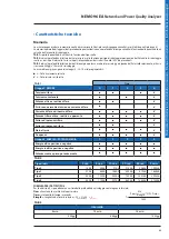
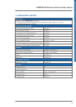
Page 43: ...in funzione del tipo scelto TAB 2 indica la profondit di lettura dati espressa in ore in funzione del tipo di salvataggio selezionato e dell intervallo di salvataggio scelto es dati tipo 0 intervallo...

Page 44: ...1 1 sec Corrente TRMS Ingresso da TA con Primario fino a 9 999 A Secondario 1 o 5 A Corrente minima di misura 5 mA Consumo delle entrate 0 2 VA Visualizzazione 0 005 A 10 kA x 1 A o 0 005 A 50 kA x 5...

Page 45: ...elettrici veloci bursts EN 61326 1 Immunit agli impulsi ad alta energia EN 61326 1 Immunit ai disturbi condotti EN 61326 1 Emissioni condotte e irradiate EN 61326 1 Classe B Immnunit ai buchi e alle...

Page 46: ...funzioni Simboli delle funzioni Classe di prestazione della funzione secondo la norma IEC 61557 12 Intervallo di misura 1 Altre caratteristiche complementari P 0 5 0 01 1 2 A x 1 A 0 05 6 A x 5 A Qa Q...

Page 47: ...zia quando il valore RMS delle tre tensioni di rete scende al di sotto di una soglia impostata e termina quando una delle tensioni sale al di sopra della soglia impostata a cui stata sommata l isteres...

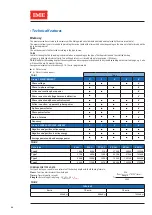
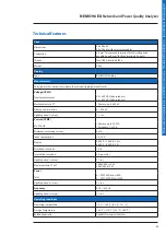
Page 48: ...ta reading expressed in hours depending on the type of backup selected and the selected backup interval e g data type 0 interval 2 min You will be able to access stored data up to the previous 1092 ho...

Page 49: ...e 30 400 V AC phase phase Measurement via PT Primary up to 300 kV Display and resolution 0 300 kV Update period on display 1 1 sec Current TRMS Via CT with Primary up to 9 999 A Secondary 1 or 5 A Min...

Page 50: ...EN 61326 1 Immunity to conducted disturbances EN 61326 1 Conducted and radiated emissions EN 61326 1 Class B Immunity to voltage dips and short interruptions EN 61326 1 Immunityto the magnetic field...

Page 51: ...nction performance class 0 5 Function features Function symbols Function performance class according to IEC 61557 12 Measuring range 1 Other complementary characteristics P 0 5 0 01 1 2 A x 1 A 0 05 6...

Page 52: ...rk voltages falls below a set threshold and ends when one of the voltages rises above the set threshold to which the hysteresis has been added 4 RVC Rapid Voltage Change is a fast variation in the pow...

Page 53: ...ype choisi TAB 2 indique la profondeur de lecture des donn es exprim e en heures en fonction du type d enregistrement s lectionn et de l intervalle d enregistrement choisie Exemple type de donn es 0 i...

Page 54: ...r affichage 1 1 sec Courant TRMS A partir du TC avec un Primaire jusqu 9 999 A Secondaire 1 ou 5 A Courant minimum de mesure 5 mA Consommation des entr es 0 2 VA Affichage 0 005 A 10 kA x 1 A o 0 005...

Page 55: ...pides en salve EN 61326 1 Immunit aux ondes de choc EN 61326 1 Immunit aux perturbations induites par les champs radio lectriques EN 61326 1 Emissions conduites et rayonn es EN 61326 1 Classe B Immuni...

Page 56: ...ques des fonctions Symb le des fonctions Classe de performance de fonctionnement conform ment la IEC 61557 12 Plage de mesure 1 Autres caract ristiques compl mentaires P 0 5 0 01 1 2 A x 1 A 0 05 6 A...

Page 57: ...trois tensions r seau tombe en dessous d un seuil d fini et se termine lorsque l une des tensions d passe le seuil d fini auquel l hyst r sis a t ajout e 4 RVC Rapid voltage change Le RVC est une var...

Page 58: ...h ngigkeitvondergew hltenSpeicherartunddemgew hlten Speicherintervall an z B Datentyp 0 Intervall 2 Min Daten k nnen bis zu den letzten 1092 Stunden abgerufen werden TAB 3 gibt den Zeitabstand der gel...

Page 59: ...VT Prim r bis 300 kV Anzeige und Aufl sung 0 300 kV Aktualisierungsperiode on display 1 1 sec Strom TRMS Eingang von CT mit Prim r bis 9 999 A Sekund r 1 oder 5 A Minimaler Messstrom 5 mA Verbrauch d...

Page 60: ...ber energiereichen Impulsen EN 61326 1 St rfestigkeit gegen ber leitungsgef hrten St rungen EN 61326 1 Leitungsgef hrte und bestrahlte Emissionen EN 61326 1 Klasse B St rfestigkeit gegen ber kurzen S...

Page 61: ...Wikenergie und Wirkleistung 0 5 Eigenschaften der Funktionen Funktionssymbole Genauigkeitsklasse der Funktion gem IEC 61557 12 Messintervall 1 Sonstige Eigenschaften P 0 5 0 01 1 2 A x 1 A 0 05 6 A x...

Page 62: ...t f llt und endet wenn eine der Spannungen ber einen festgelegten Schwellenwert steigt zu dem die Hysterese addiert wurde 4 RVC Rapid Voltage Change ist eine schnelle nderung der Versorgungsspannung S...

Page 63: ...iato alla potenza o alla tensione SyS Tipo di rete THD A THD delle correnti di fase THD V THD delle tensioni di fase o concatenate tIME Tempo di integrazione delle Correnti e Potenze Ut Rapporto di tr...

Page 64: ...s de phase ou compos es tIME Temps d int gration des Courants et Puissances Ut Rapport de transformation du TT Liste der Abk rzungen 1n1E Einphasiges Netz 3n3E Drehstromnetz 4 Leiter 3 Sensoren 3 3E D...

Page 65: ...65 NEMO 96 EA Network and Power Quality Analyzer Manuele d installazione Installation manual Manuel d installation Installationsanweisungen Notes...

Page 66: ...eitaly com www imeitaly com I M E S p A se r serve le droit de modifier tout moment le contenu de cet imprim et de communiquer sous n importe quelle forme et modalit les changements apport s I M E S p...

Reviews: