Lo strumento non necessita di particolari accorgimenti di installazione meccanici o elettrici.
Prima di procedere alla installazione, verificare che i dati di targa (tensione, corrente, fre-
quenza) corrispondano a quelli effettivi di rete.
PROGRAMMAZIONE
L’accesso alla programmazione è protetto da una chiave software costituita da una combina-
zione numerica a 4 cifre. Alla richiesta di ingresso in programmazione, lo strumento chiede
all’operatore di inserire, tramite tastiera, la combinazione di accesso, consentendo o negan-
do la possibilità di modifica dei parametri in funzione del codice impostato.
La programmazione è suddivisa su due livelli (con differenti chiavi d’accesso)
LIVELLO 1
Password 1000
= tipo inserzione, tipo potenza media, tempo di media, contrasto
display, comunicazione RS485 o uscita impulsi.
Azzeramenti di: picco corrente media, picco potenza media, contaore, energia par-
ziale.
LIVELLO 2
Password 2001
= rapporto trasformazione TA e TV esterni
Per la programmazione vengono utilizzati i 3 tasti posti sul frontale:
DOWN + ENTER
ingresso programmazione
ENTER
conferma dati
DOWN
spostamento cursore
UP
incremento valore impostato
In fase di programmazione,
DOWN + ENTER
uscita programmazione (senza salvataggio
modifiche)
Nei casi in cui la programmazione è impostabile a passi fissi (es. tipo connessione, azzeramen-
to valori, ecc) i tasti
DOWN e UP
permettono di selezionare i valori disponibili.
PARAMETRI PROGRAMMABILI
• PASSWORD 1000
CONNESSIONE
Lo strumento può essere utilizzato per inserzione su linea monofase o trifase (3 o 4 fili).
Scegliere il tipo di inserzione desiderata e rispettare scrupolosamente nei cablaggi lo schema
di inserzione. Una inesattezza nei collegamenti è inevitabilmente causa di misure falsate o di
danni allo strumento.
La configurazione dell’ingresso, deve essere completata con la programmazione da tastiera
del tipo di inserzione selezionato e degli eventuali rapporti TA e TV esterni.
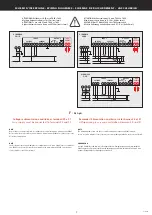
Inserzioni realizzabili:
1n1E
schema
S1000/220
linea monofase
3-2E
schema
S1000/213
linea trifase 3 fili, 2 sistemi Aron
3-3E
schema
S1000/282
linea trifase 3 fili, 3 sistemi
3n3E
schema
S1000/212
linea trifase 4 fili
ATTENZIONE! accertarsi della esatta corrispondenza tra lo schema di inserzione
utilizzato e la programmazione del tipo inserzione effettuata da tastiera.
VERIFICA SEQUENZA FASI
Premendo
ENTER
viene effettuato un controllo del corretto collegamento delle voltmetriche
(sequenza fasi). Se il collegamento è errato appare la visualizzazione ERR 123.
In questo caso occorre correggere il collegamento delle voltmetriche e ripetere la verifica fino ad
ottenere l’esatta sequenza.
ATTENZIONE!
Una errata sequenza fasi è causa di errori di misura
.
ENERGIA
Azzeramento:
energia attiva parziale
POTENZA MEDIA / CORRENTE MEDIA
Tempo integrazione:
5, 8, 10, 15, 20, 30, 60 minuti
Potenza associata:
attiva, reattiva, apparente
Azzeramento:
valore massimo potenza media e corrente media
CONTAORE
Azzeramento:
ore, minuti di funzionamento
USCITA IMPULSI
(dove prevista)
Energia associata:
attiva o reattiva
Peso impulsi:
1imp/0,1kWh - 1imp/kWh - 1imp/10kWh - 1imp/100kWh (kvarh)
Durata impulso:
50 – 100 – 200 – 300ms
COMUNICAZIONE RS485
(dove prevista)
Indirizzo:
1...255
Velocità comunicazione:
4,8 – 9,6 – 19,2 Kbit/sec
Bit di parità:
nessuna - pari - dispari
Tempo massimo fra i caratteri del messaggio:
3...100ms
(Time-out)
Normalmente è consigliabile impostare 003 (3ms).
In caso di assenza di comunicazione, nell’abbinamento ad altre interfacce, provare ad
aumentare il valore.
Nel caso lo strumento sia inserito in rete con altri dispositivi IME, di tipo differente, impostare
20ms.
• PASSWORD 2001
RAPPORTO TRASFORMAZIONE TRASFORMATORI ESTERNI
Ct
= primario TA 100/1A - 150/1A - 250/1A - 400/1A - 600/1A - 1/1A
Vt
= rapporto primario/secondario TV (es. TV600/100V Vt=6)
ATTENZIONE: per inserzione diretta in tensione(senza TV esterno)
impostare Vt=01.0
VISUALIZZAZIONE
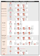
Il menù di visualizzazione è suddiviso in differenti pagine, e varia in funzione del tipo di
inserzione selezionato. Per scorrere le pagine di visualizzazione premere
DOWN.
Per ritornare alle pagine precedenti premere
UP.
CONTAORE (ore e minuti di funzionamento)
La funzione contaore, conteggio ore e minuti di funzionamento, è attiva quando il dispositi-
vo rileva la presenza della fase
L1
.
The meter does not need any specific mechanical or electrical mounting contrivance.
Before mounting, it is necessary to verify that data on the label (voltage, current, frequency)
correspond to the real network ones.
PROGRAMMING
Access to programming is protected by a software key composed of a 4-digit numeric combi-
nation. When one wants to enter the programming mode, the meter prompts the operator
to type the access combination, allowing or denying, according to the loaded code, the possi-
bility to modify the parameters.
Programming is subdivided on two levels (with different access keys).
LEVEL 1
Password 1000
= connection type, type of average power, average time, display
contrast, RS485 communication or pulse output.
Reset of: average current peak, average power peak, run hour meter, partial
energy.
LEVELL 2
Password 2001
= external C.T. and V.T. transformer ratio
For programming are used the 3 keys on the front board:
DOWN + ENTER
to enter the programming
ENTER
to confirm the data
DOWN
to shift the cursor
UP
increases the loaded value
During the programming,
DOWN + ENTER
to leave the programming (without backing up
the modifications)
In the cases where the programming can be loaded by fixed steps (for instance connection
type, value reset, etc.)
DOWN and UP
keys allow selecting the available values.
PROGRAMMABLE PARAMETERS
• PASSWORD 1000
CONNECTION
The meter can be connected with single-phase or 3-phase lines (3 or 4 wires).
Choose the desired connection and, in the wiring, scrupulously respect the wiring diagram.
An error in connection unavoidably leads to wrong measurements or damages to the meter.
The input configuration must be completed with the keyboard programming of the chosen
connection type as well as of any external current and voltage transformer ratios.
Possible connections:
1n1E
wiring diagram
S1000/220
single-phase line
3-2E
wiring diagram
S1000/213
3-phase line, 3 wires, 2 Aron systems
3-3E
wiring diagram
S1000/282
3-phase line, 3 wires
3n3E
wiring diagram
S1000/212
3-phase line, 4 wires
WARNING! Pay attention that the used wiring diagram meets the keyboard-
programming configuration.
PHASE SEQUENCE CHECKING
Pressing
ENTER
, a check of the correct connection of the voltmetric (phase sequence) is carried out.
If the connection is wrong, Err 123 YES is displayed.
In this case you have to correct the voltmetric connection and repeat the checking until you get the
correct sequence.
ATTENTION!
A wrong phase sequence may lead to measuring errors.
ENERGY
RESET:
partial active energy
POWER DEMAND / CURRENT DEMAND
Delay time:
5, 8, 10, 15, 20, 30, 60 minutes
Combined power:
active, reactive, apparent
Reset:
power max demand and current demand
RUN HOUR METER
Reset:
working hours and minutes
PULSE OUTPUT
(where applicable)
Combined energy:
active or reactive
Pulse frequency:
1imp/0,1kWh - 1imp/kWh - 1imp/10kWh - 1imp/100kWh (kvarh)
Pulse duration:
50 – 100 – 200 – 300ms
RS485 COMMUNICATION
(where applicable)
Address:
1...255
Baud rate:
4,8 – 9,6 – 19,2 Kbit/sec
Parity bit:
none - even - odd
Time-out:
3...100ms
It is normally advisable to load 003 (3ms).
If in connecting the meter with other interfaces the communication is lacking, try to increase
the value.
If the meter is connected to the net with other IME devices of different type, load 20ms
• PASSWORD 2001
C.T. – V.T. TRANSFORMER RATIO
Ct
= CT primary 100/1A - 150/1A - 250/1A - 400/1A - 600/1A - 1/1A
Vt
= voltage primary/secondary transformer ratio (ex. VT 600/100V Vt=6)
WARNING: for voltage direct connection
(without external VT)
, load Vt=01,0
DISPLAY
Display menu is subdivided into different pages and it changes according to the selected con-
nection type. To scroll the display pages press
DOWN.
To return to the previous pages press
UP
.
HOUR METER (working minutes and hours)
Run hour function, working minutes and hour counting, is operating when the device
detects
L1
phase.
ISTRUZIONI PER L’INSTALLAZIONE
MOUNTING INSTRUCTIONS
10782802W
3


