background image

 IMER INTERNATIONAL S.p.A.

MIX 360

11

-Start the motor, following the instructions contained in the motor ma-
nual.
-Allow the motor to warm up at reduced rpm.
-Increase the rpm to maximum using the accelerator lever mounted on 
the frame.
Machines with an endothermic motor are fi tted with a centrifugal expan-
ding clutch mounted on the motor.
The clutch enables the paddle rotation speed to be increased gradually, 
which can be stopped when the motor is operating at minimum rpm.
Motor operating speed can be controlled by means of the accelerator 
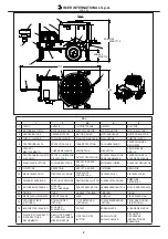
lever (rif. 5, tab. 9).

9.2 WORKING CYCLE

. WARNING! Check that the machine stops rotating when the 

tank protection cover is lifted.

Start-up the machine with the tank empty.
-With the water supply connected to the mains, start feeding water by 
opening the valve mounted on the tank, and add the cement and ag-
gregate.
-The tank protection grid is fi tted with a bag splitter to enable pre-packed 
mixes to be used.
-When the mix has reached the required consistency, place a suitable 
container under the outlet and, keeping the paddles moving, open the 
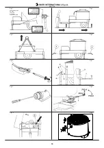
outlet using lever Ref. 1 (see Fig. 9). 
Lift the lever to position A and push it as far as possible to position B. 
To close the outlet, return the lever to Pos. C.

. Avoid starting the machine with a full load. 

Do not overfi ll the tank (see 3. MIXING CAPACITY).

10. EMERGENCY STOP

. In the event an electric motor fault, press the OFF pushbutton 

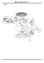
(Ref. 17 Fig. 1) and disconnect the mixer from the power supply.
In the case of endothermic motors, move the acceleration lever to 
the minimun position.

. The motor is protected from thermal overloads. If it overheats 

it will stop. It must be allowed to cool before restarting.

11. MAINTENANCE

. WARNING! Before carrying out any form of maintenance 

work, always switch off the mixer.

-Replace worn or faulty components using original spare parts.
-Check the oil level through the transparent level indicator on the side of 
the reduction gear casing.
-Change the oil in the reduction gear with SAE 90 oil after 2000 hours of 
work (approximately 0.9 Kg).
-To top up or replace the oil, used the fi ller pipe (ref. 1, fi g. 10). Lift the 
motor casing to gain access to the fi ller.

. Used oil is classifi ed as special waste and must be treated as 

such in accordance with laws in force.

. Always ensure that writing and other instructions on the ma-

chine are legible.

. Always ensure that the protection devices are undamaged 

and effi cient.

-At the end of the work session, remove dirt and/or any other deposits 
formed during mixing by washing thoroughly (to wash the machine, use 
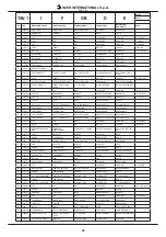
the wash-water hose with pressure regulator, Ref. 51 Tav. 1, mounted 
on the mixing tank valve).

. Check the condition of the power cable before using the machi-

ne; it may have become inadvertently or unknowingly damaged.

-Check the endothermic motor according to the instructions contained 
in the motor manual.
If guards are removed due to maintenance requirements or other excep-
tional circumstances, proceed as described below, and always refi t the 
guards before resuming operation.

11.1 COVER PROTECTION ADJUSTMENT(FIG. 11)

The adjustment of the limit switch must be carried out with the tank 
protection cover lowered. 
Move the limit switch to the correct position using the slots and re-ti-
ghten the screws for disel engine.
The fi lling side cover grid opening is protected by a  interlocked cut off 
device that stops the engine as the protection cover is lifted, the adju-
stment is carried out by correcting the lenght of the wire and re-tighten 
the screw.

. WARNING

Check that the machine stops when the tank protection cover is 
lifted

11.2 OUTELET PROTECTION REMOVAL (Réf.Fig.12)

- Slacken screws Ref. 2 and remove protection Ref. 1. 
- To replace the protection, align the holes with those of brackets Ref. 3 
and tighten with screws Ref. 2. Use spanner N°13.

11.3 MIXING PADDLE REPLACEMENT (Fig.13)

- Lift the tank protection grid Ref. 1.
- Remove head protection Ref. 2, rotating it in an anti-clockwise direc-
tion.
- Slacken screws Ref. 3 and nuts Ref. 4. Use open-ended spanner N°17 
and Allen key N*6.
- Remove the paddle clamps Ref. 5, 6 and 7 and replace the worn rub-
bers Ref. 8, 9 and 10. Inserting the new rubbers between holders Ref. 
11, 12 and 13 and clamps Ref. 5, 6 and 7. Utilize the slots to adjust as 
necessary and lock in position with nuts and bolts Ref. 3 and 4.
- Push arm Ref. 14 to manually rotate the paddles in a clockwise direc-
tion, checking the mating of the rubbers with the tank.
- If there are zones where the rubber is not in contact with the tank, 
repeat the adjustment. Re-adjust utilizing the slots in brackets Ref. 15 
and 16 if necessary. 
- Replace and lock in position protection Ref. 2, rotating it in a clockwise 
direction. Lower the cover grid Ref. 1.

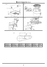
11.4 TENSIONING AND REPLACING TRANSMISSION BELTS


11.4.1 MIXERS FITTED WITH ELECTRIC MOTOR 

 (Fig. 

14)

1. Unscrew the locking screws and lift the motor casing. 
Use spanner N°6.
2. To tension the belts, slacken nut Ref. 1, tighten nut Ref. 2 and re-
tighten nut Ref.1. Use spanner N*19.
3. To replace the belts, slacken nut Ref. 23?? and nut Ref. 1, remove the 
old belts. Replace them with new belts of same characteristics. Tension 
as described in point 2.
4. Lower the casing and lock in position with the locking screws.


11.4.2 MIXERS FITTED WITH ENDOTHERMIC MOTORS


 (Fig. 15)

1. Unscrew the locking screws and lift the motor casing. Use spanner 
N°17.
2. To tension the belts, slacken nut Ref.1, tighten nut Ref.2 and re-ti-
ghten nut Ref.1.
3. To replace the belts, slacken nuts Ref.1 and Ref.2, remove the old 
belts. Replace with new belts of same characteristics. Tension as de-
scribed in point 2.
4. Lower the casing and lock in position with the locking screws.
- Check the tension of the transmission belts after 4 hours from fi rst 
start-up and after each belt change, otherwise check the tension every 
18-20 hours.

. When replacing transmission belts, remember that a too tight 

belt will cause damage to shafts and bearings, a too slack belt will 
wear out rapidly.


11.4.3 REQUIREMENTS FOR CORRECT TRANSMISSION


 BELT TENSIONING (Fig. 16)

To ensure correct tension of the transmission belts, apply a force “F” 
(0.9 kg) on the centre of section “S”; distance “f” should be as specifi ed 
in the table in Fig. 16.

GB

Summary of Contents for MIX 360

Page 1: ... 50Hz 1194595 Honda 1194596 Hatz I MESCOLATRICE Manuale di uso manutenzione e ricambi F MELANGEUSE Manuel utilisation entretien pieces de rechange GB MIXER Operating maintenance spare parts manual D MISCHER Handbuch für Bedienung Wartung und Ersatzteile E MEZCLADORA Manual de uso mantenimiento y recambios 3211080 R04 2012 02 MIX 360 ...

Page 2: ...IA RIDUTTORE POUILE RÉDUCTEUR REDUCTION GEAR PULLEY ANTRIEBSSCHEIBE POLEA DEL REDUCTOR 9 RIDUTTORE RÉDUCTEUR REDUCTION GEAR GETRIEBE REDUCTOR 10 PIEDE TELESCOPICO PIED TÉLESCOPIQUE TELESCOPIC SUPPORT LEG TELESKOPFUSS PIE TELESCOPICO 11 FRIZIONE CENTRIFUGA FRICTION CENTRIFUGE CENTRIFUGAL CLUTCH FLIEHKRAFTKUPPLUNG EMBRAUGE CENTRIFUGO 12 MOTORE ENDOTERMICO MOTEUR ENDOTHERMIQUE ENDOTERMIC MOTOR VERBRE...

Page 3: ...imensioni imballo Dimensions emballage Packing dimensions Abmessungen der Verpackung Dimensiones del embalaje mm 1680x1080x1155 Potenza motore Poissance moteur Motor rating Motorleistung Potencia del motor Kw 3 0 400V 50Hz Kw 8 1 Honda 340GXV Kw 7 0 Hatz 1 B40V Direzione rotazione pale Orario Direction rotation palettes Sens horloge Paddle rotation direction Clockwise Schaufeldrehrichtung Im Uhrze...

Page 4: ...amente l apposito interruttore Non aprire la protezione vasca per fermare la mescolatrice 5 SICUREZZA ELETTRICA La mescolatrice per malta IMER risponde alle norme EN60204 1 in particolare è dotata di Un sistema che impedisce il riavviamento automatico dopo un interru zione sulla linea di alimentazione Protezione magnetotermica dell equipaggiamento elettrico Dispositivo elettrico di sicurezza che i...

Page 5: ...l manuale motore fornito assieme alla macchina Qualora eccezionalmente per manutenzione si renda necessario toglie re le protezioni procedere come indicato nei seguenti paragrafi avendo sempre cura di rimontarle prima di rimettere in uso la macchina 11 1 REGOLAZIONE PROTEZIONE VASCA Rif Fig 11 La regolazione del finecorsa deve essere effettuata con il coperchio va sca abbassato Per la regolazione ...

Page 6: ...NTO La bocchetta di scarico non apre Depositi nella protezione bocchetta Rimuovere e pulire la protezione bocchetta 11 2 RIMOZIONE PROTEZIONE VASCA Durenate l impasto le pale diminuiscono i giri o si arrestano Le cinghie sono lenti o slittano Tensionare le cinghie 11 4 TENSIONAMENTO E SOSTITUZIONE CINGHIE DI TRASMISSIONE Non arriva acqua Non viene acqua della tubazione di alimentazione Controllare...

Page 7: ...é Ne pas mettre la mélangeu se en fonction pendant les opérations d entretien et de réparation Dans la zone de travail il est nécessaire de respecter les normes pour la prévention des accidents ainsi que les dispositions de sûreté Pour arrêter la mélangeuse utiliser exclusivement l interrup teur prévu à cet effet Ne pas ouvrir la protection cuve pour arrêter le malaxeur 5 SÉCURITÉ ÉLECTRIQUE La mé...

Page 8: ...seau hydrique Vérifier systématiquement l état du câble électrique à chaque début d utilisation de la machine Il est possible qu il ait été acci dentellement et ou inconsciemment endommagé Contrôler le moteur endothermique selon les instructions du manuel moteur S il s avère nécessaire de démonter les protections pour les opérations d entretien procéder en suivant les instructions des paragraphes ...

Page 9: ...placer le caoutchouc le ressort est cassé ou non efficace remplacer le ressort Les caoutchoucs n adhèrent pas caoutchoucs usés remplacer les caoutchoucs et ou ajuster leur position 11 3 SUBSTITUTION PALETTES DE MALAXAGE La bouche d évacuation ne s ouvre pas dépôts dans la protection de la bouche enlever et nettoyer la protection bouche 11 2 DEPLACEMENT PROTECTION CUVE Durant le malaxage les palett...

Page 10: ...ly be stopped using the appropriate switch Do not open the tank protection cover to stop the machine 5 ELECTRICAL SAFETY The IMER mixer complies with standards EN60204 1 In particular it is equipped with a system that prevents automatic restart after the power supply line is interrupted Residual current protection of electrical equipment Electrical safety device that prevents the machine from oper...

Page 11: ...nd always refit the guards before resuming operation 11 1 COVER PROTECTION ADJUSTMENT FIG 11 The adjustment of the limit switch must be carried out with the tank protection cover lowered Move the limit switch to the correct position using the slots and re ti ghten the screws for disel engine The filling side cover grid opening is protected by a interlocked cut off device that stops the engine as t...

Page 12: ...t will not open Depositin the outlet protector Remove and clean the outlet 11 2 REMOVAL OF TANK PROTECTION COVER During mixing the paddle rpm decreases or paddles stop Belts are slack and are slipping Tension the belts 11 4 TENSIONING AND REPLACING TRANSMISSION BELTS Water does not arrive at the tank There is no water in the feed line Change the feed line Water hose or valve blocked Clean the hose...

Page 13: ...zen Im Betriebsbereich sind die Unfallschutz und Sicherheitsvorschriften zu befolgen Zum Anhalten des Mischers ausschließlich den dafür vorge sehenen Schalter verwenden Nicht die Trogabdeckung zum Anhalten des Mischers öffnen 5 ELEKTRISCHE SICHERHEIT Der IMER Mörtelmischer ist nach EN60204 1 gebaut Er verfügt über ein System das den automatischen Neustart nach einem Stromausfall verhindert Magneto...

Page 14: ...r unversehrte Zustand des Netzkabels zu prüfen da es jemand unbemerkt bzw unwissentlich beschädigt haben könnte Den Verbrennungsmotor nach den Anweisungen des Motorhandbu ches kontrollieren Falls die Schutzvorrichtungen für Wartungsarbeiten ausnahmsweise entfernt werden müssen wie in den vorstehenden Absätzen beschrie ben vorgehen und vor dem erneuten Einsatz der Maschine die Verklei dungen unbedi...

Page 15: ... ihre Position richten 11 3 ERSATZ DER MISCHER SCHAUFELN Die Bodenklappe öffnet sich nicht Ablagerungen an der Trogabdeckung Die Trogabde ckung entfernen und säubern 11 2 ABBAU DER TROGAB DECKUNG Während dem Mischen nimmt die Drehzahl der Schaufeln ab oder sie halten an Die Riemen sind locker und schlupfen Die Riemen spannen 11 4 SPANNEN UND WECHSELN DER ANTRIEB SRIEMEN Es wird kein Wasser geliefe...

Page 16: ... todas las normas para la pre vención de accidentes así como las disposiciones de seguridad Para parar a la mezcladora hay que utilizar solamente el inter ruptor correspondiente No abrir la protección del recipiente para parar a la mezcla dora 5 SEGURIDAD ELÉCTRICA La mezcladora para argamasa IMER responde a las normas EN 60204 1 y concretamente está dotada Un sistema que impide la puesta en march...

Page 17: ...l estado del cable eléctrico cada vez que se pone en marcha la máquina ya que puede haber sido dañado inadver tidamente Controlar el motor endotérmico según las instrucciones del manual del motor Si para llevar a cabo el mantenimiento es preciso quitar las proteccio nes proceder como se indica en los apartados que siguen y volver a montar las protecciones antes de poner la máquina nuevamente en fu...

Page 18: ...ección de la boca 11 2 EXTRACCIÓN DE LA PROTECCIÓN DEL RECIPIENTE Durante el mezclado las palas se paran o reducen la velocidad Las correas están flojas y resbalan Tensar las correas 11 4 TENSADO Y SUSTITUCIÓN DE LAS CORREAS DE TRANSMISIÓN No llega agua No pasa agua por el tubo de alimentación Cambiar la alimentación El tubo de agua o el grifo están atascados Limpie el tubo y o el grifo Al levanta...

Page 19: ...3 Fig 4 Fig 5 Fig 6 Fig 7 Fig 8 Fig 9 Fig 10 Fig 11 VITE DI TERRA VIS DE TERRE EARTH SCREW ERDUNGSSCHRAUBE TORNILLO DE TIERRA CAVO DI TERRA CABLE DE TERRE EARTH CABLE ERDUNGSKABLE CABLE DE TIERRA SUPPLEMENTARE DE PLUS FURTHER WEITERE SUPLEMENTARIO ...

Page 20: ...Fig 15 Fig 16 Macchina con Machine avec Mchine With Maschine mit Máquina con f mm Motore elettrico Moteur électrique Electric motor Elektromotor Motor eléctrico 10 Motore endotermico Moteur endothermique Endothermic motor Verbrennungsmotor Motor endotérmico 8 ...

Page 21: ...olgenden Angaben machen 1 Maschinentyp 2 Jeweils zugeordnete Art Nr und Posi tionsnummer 3 Seriennummer und Baujahr Angabe auf dem Maschinenschild SYMBOLE Austauschbarkeit Beispiel Bis zur Maschinenummer 5240 ist Ref 1 Cod 3204530 und ab Maschinennummer 5241 ist Ref 1 1 Cod 3204520 installiert worden Ref 1 1 und Ref 1 sind austaschbar Ref 1 und Ref 1 1 sind nicht austauschbar wenn das Symbol angeg...

Page 22: ...PLETA 26 3211028 PALA COMPLETA PALETTE COMPLETE PADDLE ASSEMBLY KOMPLETTE SCHAUFEL PALA COMPLETA 27 2222599 VITE VIS BOLT SCHRAUBE TORNILLO 5933 M10X15 28 2223655 DADO ECROU NUT MUTTER TUERCA 5589 M10 29 3211607 RASCHIATORE PERIFE RICO RACLEUAR PÉRIPHÉRIQUE PERIPHERAL S CRAPER UMLAUFSCHAUBER RASCADOR PERIFÉRI CO 30 2294771 PALA PALETTE PADDLE SCHAUFEL PALA 31 2250934 GOMMA CAOUTCHOUC RUBBER GUMMIP...

Page 23: ...IMER INTERNATIONAL S p A MIX 360 23 TAV 1 ...

Page 24: ...LATION JOINT GELENK ARTICULACIÓN 6 2209822 BRONZINA COUSSINET BUSH BRONZEBUCHSE COJINETE 7 2222600 VITE VIS BOLT SCHRAUBE TORNILLO 963 M6x26 8 2225033 DISCO DISQUE DISC SCHEIBE DISCO 9 2292581 GUARNIZIONE JOINT GASKET DICHTUNG JUNTA 10 2253863 DISCO DISQUE DISC SCHEIBE DISCO 11 2223924 DADO ECROU NUT MUTTER TUERCA 12 2223920 DADO AUTOBLOCCANTE ECROU DE SÛRET SELF LOCKING NUT SELBSTSICHERNDE MUTTER...

Page 25: ... 1 3208128 ASSALE ESSIEU AXLE ACHSE ÁRBOL 2 3210607 VITE VIS BOLT SCHRAUBE TORNILLO 3 3201789 RUOTA ROUE WHEEL RAD RUEDA 4 2222142 VITE VIS BOLT SCHRAUBE TORNILLO 5737 M12X100 Z 5 3207392 DADO AUTOGRIPPANTE ECROU DE SÛRETE SELF LOCKING NUT SELBSTSICHERNDE MUTTER TUERCA AUTOBLOCANTE METAL BLOC M12 6 2224380 ROSETTA RONDELLE WASHER UNTERLEGSCHEIBE ARANDELA 6593 D 12X25 Z ...

Page 26: ...52 CARTER CARTER CASING GEHÄUSE CÁRTER Honda Hatz 18 2292298 MOSCHETTONE MOUSQUETON SPRING CATCH KARABINERHAKEN MOSQUETÓn 19 2292370 TUBO GOMMA TUYAU EN CAOUTCHOUC RUBBER HOSE SCHLAUCH TUBO DE GOMa 20 2223570 DADO ECROU NUT MUTTER TUERCA 5588 M8 21 3211110 TARGHETTA PLAQUETTE IDENTIFICATION PLATE SCHILD PLACa 400v 50Hz 3211106 TARGHETTA PLAQUETTE IDENTIFICATION PLATE SCHILD PLACa Honda 3226905 TAR...

Page 27: ...04510 CUSCINETTO ROULEMENT BEARING LAGER COJINETE 13 2224140 ROSETTA RONDELLE WASHER UNTERLEGSCHEIBE ARANDELA Ø 8X18 14 2222006 VITE VIS BOLT SCHRAUBE TORNILLO 5739 M8X30 15 2236735 FLANGIA BRIDE FLANGE FLANSCH BRIDA M 21 16 2204550 CUSCINETTO PALIER BEARING LAGER COJINETE 6205 17 2229450 LINGUETTA LANGUETTE KEY FEDER LENGÜETA 8X7X20 18 2202858 PIGNONE PIGNON PINION RITZEL PIÑÓN 19 2202871 PIGNONE...

Page 28: ... 3228506 MOTORE MOTEUR ELECTRIC MOTOR ELEKTROMOTOR MOTOR ELECTRICO Kw 3 400V 50Hz 17 2205581 PULEGGIA POULIE PULLEY RIEMENSCHEIBE POLEA DP 100 2A 18 2223600 DADO ECROU NUT MUTTER TUERCA 5588 M10 19 2224206 ROSETTA RONDELLE WASHER UNTERLEGSCHEIBE ARANDELA 6592 12X36X4 20 2222768 VITE VIS BOLT SCHRAUBE TORNILLO 5739 4S M12X90 21 3211057 PORTAMOTORE PORTE MOTEUR MOTOR MOUNTING PLATE MOTORHALTERUNG PL...

Page 29: ...IMER INTERNATIONAL S p A MIX 360 29 TAV 7 37 16 23 21 17 1 15 4 13 12 1 13 13 28 18 1 8 36 ...

Page 30: ... RONDELLA RONDELLE WASHER UNTERLEGSCHEIBE ARANDELA DEV Ø8Z C72 18 2221994 VITE VIS BOLT SCHRAUBE TORNILLO UNF5 16 X25Z 19 2205529 PULEGGIA POULIE PULLEY RIEMENSCHEIBE POLEA DP450 2A 20 3211422 CINGHIA COURROIE BELT RIEMEN CORREA AX89 21 3211047 PROTEZIONE PROTECTION PROTECTION VERKLEIDUNG PROTECCIÓN 22 2289357 FRIZIONE CENTRALE EMBRAYAGE CENTRAL CLUTCH ZENTRALKUPPLUNG EMBRAGUE CENTRAL 23 2224340 R...

Page 31: ...IMER INTERNATIONAL S p A MIX 360 31 TAV 8 ...

Page 32: ...TION LEG EXTENSION KIT OPTIONAL FUSSVERLÄNGERUNG OPTIONSAUSRÜSTUNG KIT DE PROLONGACIÓN OPCIONAL NOTE 1 3200457 Prolunga gambe Rallonge pieds Leg extension Fußverlängerung Prolongación patas 2 2227048 Anello portachiavi Bague porte cles Key ring Schlüsselring Anillo portallaves 3 2226715 Copiglia Goupille Split pin Splint Pasador M 12 ...

Reviews: