background image

10

  MASONRY 500

IMER INTERNATIONAL S.p.A.

GB

GB

  -  Turn  off  the  engine  before  topping  up  the  tank  with

petrol.

Saws with endothermic engines must be used in the open air. If they

have to be used in closed environments, the openings must be provided

to conduct gases from the engine’s exhaust pipe to the outside using

appropriate non-flammable flexible tubes.

These must be checked for leaks and breakages at the beginning of

every  shift.

 -  Do not start the machine with the blade in the workpiece.

When the saw is not being used, turn the petrol cock to the OFF

position.

10.1  STARTING  ROTATION  OF  THE  CUTTING  WHEEL.

Gradually move the lever (ref.19; fig.1) so as to bring the motor

revs up to normal working speed and start the wheel turning at

the cutting speed foreseen.

11.  STARTING  THE  MACHINE

Before  cutting:

1 – Check that there is enough cooling water in the tank.

2 - adjust the flow of cooling water by turning the cock next to

the blade guard (do not perform cutting without water).

3 - Ensure that blade rotation corresponds to the indications on

the blade guard.

4 – If everything is in order, work can begin.

12.  EMERGENCY  -  STOP

 -


In  an  emergency,  stop  the  machine  by  pressing  the

stop  control  switch  (ref.  7,  fig.  1).

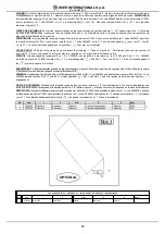
13.  BLADE  INSTALLATION  (Fig.5)

By means of a hex wrench no.10, unscrew the 5 screws that lock

the moving blade guard (ref.3). Loosen the locknut (rif.1) by rotating

clockwise (left thread). Remove the mobile flange (rif.2) and check

that the flanges, disc shaft and blade are not damaged.

 -


Never use worn blades or blades with missing segments.

  -  Only  use  blades  that  are  designed  for  the  number  of

revolutions  indicated  on  the  machine  rating  plate.

  - Check that blade rotation corresponds to that indicated

on  the  blade  guard.

Centre the blade against the fixed flange, position the mobile flange

and tighten the blade locknut fully down by rotating anticlockwise

(left thread). Refit the moving blade guard, tightening the 5 screws

(ref.3).

    -  Ensure  that  the  blade  guard  (ref.3)  is  locked

securely  into  position.

    -  WARNING!  An  incorrectly  installed  blade,  or  a

screw  insufficiently  tightened  can  provoke  damage  to
the  machine  or  injury  to  persons.

    -  Note  that  the  blade  must  have  an

external  diameter  of  500  mm,  a  central
hole  diameter  of  25.4  mm  and  max.
thickness  of  3  mm.

    -  Check  that  the  blade  to  be  used  is

suitable  for  the  material  to  be  cut.

  - Do not use blades for wood! (fig. 6).

14. USE

    -  Leave  a  space  of  at  least  150  cm

around  the  machine  to  operate  in  full  safety.

- Do not allow other persons to approach the machine during cutting.

- Never use the machine in fire-risk areas. Sparks can cause fire or

explosions.

- Make sure that the machine is switched off before positioning or

handling.

- Always ensure that the blade is free of any contact before start-up.

  - Ensure correct installation of all protective devices.

- Before starting work, fill the water tank. Top up during operation

whenever  necessary:  N.B.

  the  pump  suction  hose  must

always  remain  immersed  in  water.

  -  WARNING!  For  safety  purposes  the  removal  of

protective  guards  from  the  machine  is  strictly  prohibited.

    -


WARNING!  Always  switch  off  the  machine  before

carrying  out  blade  adjustment.

Loading and unloading pieces on the machine cutting table. To avoid

the risk of accidental contact with the cutting wheel, the pieces must

be positioned and removed from the carriage with the cutting wheel

stopped.  This is done by adjusting the lever (ref.19; fig.1) so as to

reduce the revs to minimum, thus disengaging the clutch.

14.1 VERTICAL MOVEMENT OF THE DISK.

To raise or lower the cutting wheel, turn the crank (ref.11, fig.1)

until the wheel is at the required height above the cutting table.

The  wheel  can also  be  lowered  by  pressing the  pedal  (ref.16,

fig.1); when the pedal is released the cutting wheel will return to

the position originally set using the crank.

  -


Ensure  that  the  locking  handle  is  tightened  fully

before  starting  work.

14.2  POSITIONING  FOR  45°  CUTS.

To  machine  a 45°  cut,  it  is  necessary  to use  the  45°  support.

Place the 45° support on the cutting table in the position required,

fix the support to the carriage by locking the flywheel provided,

then position the piece to be cut, after which it is possible to start

the motor and commence cutting operations

14.3  CUTTING

For  safe  use  of  the  machine  when  cutting,  push  the  carriage

forwards  as  the  cut  advances,  placing  your  hands  to  the  two

sides of the carriage.  Never push directly on the piece to be cut.

  -


Check  that  the  blade  is  aligned  with  the  cutting  line.

-  Place  the  workpiece  on  the  worktable  (ref.  8,  fig.  1),  resting

firmly against the stop.

- Start the engine.

- Wait until the water reaches the blade.

- Begin cutting.

- Horizontal cutting movement is carried out by pulling the carriage

towards  the  blade.

  -


As  cutting  thickness  increases,  the  blade  is

subjected  to  greater  stress.  To  avoid  overloading  the
engine,  the  operator  should  continually  check  blade
feed  speed.  The  speed  wi ll  also  depend  on  the
characteristics  of  the  material  being  cut  (hardness,
toughness  etc.).

14.3.1  CUTTING  WITH  CUTTING  WHEEL  LOWERED
FROM  ABOVE.

Adjust  the  vertical  height  by  turning  the  crank  (ref.11,  fig.1),

position the piece to be cut, start the panel saw and commence

cutting operations by pressing the pedal (ref.16, fig.1) to lower

the  wheel from  above.

14.3.2 BLADE CHANGE

To change the blade refer to section 13.

15.  USING  550  DIAMETER  CUTTING  WHEEL.

If an optional cutting wheel diameter 550 mm is used instead of

the standard wheel diameter 500 mm, it is important that the

stop  bolt  be  calibrated  to  prevent  interference  between  the

wheel and the carriage when the head is in the lowest position.

 -  Warning. The panel  saw is fitted  with a stop  bolt to

stop  the  cutting  wheel  in  the  lowest  vertical  position.
This stop is calibrated for a 500 mm cutting wheel.  If you
are  using  a  550  mm  cutting  wheel,  loosen  the  bolt  (ref.
17,  fig.  1),  lower  the  wheel  to  the  lowest  position,  by
turning  the  crank,  then  check,  with  the  motor  turned  off,
that  there  is  no  interference  between  the  cutting  wheel
and  the  piece  holder  carriage  when  the  pedal  is  pressed.
Adjust  the  bolt,  bring  it  into  contact  with  the  stop  and
tighten  the  lock  nut.

  -  Note that the blade must have an external diameter

of  550  mm,  a  central  hole  diameter  of  25.4  mm  and  max.
thickness  of  3  mm.

Fig. 6

Summary of Contents for MASONRY 500

Page 1: ...m MASONRY 500 1188806 3210336 R03 2010 01 I SEGATRICE Manuale di uso manutenzione e ricambi F SCIE Manuel utilisation entretien pieces de rechange GB SAWING MACHINE Operating maintenance spare parts manual D MASCHINENSÄGE Handbuch für Bedienung Wartung und Ersatzteile E TRONZADORA Manual de uso mantenimiento y recambios ...

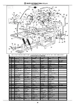
Page 2: ... couper 13 Lame 14 Châssis 15 Vis de terre 16 Pédale 17 Boulon de butée tête 18 Protection lame 19 Levier accélérateur GB 1 Carriage locking lever 2 Spray guard 3 Engine 4 Blade support 5 Water pump 6 Guide 7 Emergency switch 8 Worktable 9 Water tank 10 Blade cover 11 Adjustment crank 12 Work piece 13 Blade 14 Frame 15 Earth screw 16 Pedal 17 Head stop bolt 18 Blade guard 19 Accelerator lever I 1 ...

Page 3: ...o essere usate esclusivamente lame diamantate a corona conti nua o a settori vedere paragrafo 13 sempre refrigerati ad ac qua Non si devono assolutamente usare lame per taglio a secco e non si deve tagliare altro materiale non previsto in questa specifica IMER INTERNATIONAL declina ogni responsabilità sui danni derivati da un uso improprio dell apparecchiatura 5 CAPACITÀ DI TAGLIO disco diametro 5...

Page 4: ...Rimontare il carter mobile del disco serrando le 5 viti rif 3 Assicurarsi che il carter disco rif 3 sia ben fissato ATTENZIONE Un disco non correttamente montato una vite di bloccaggio non sufficientemente serrata pos sono provocare danni alla macchina e alle persone Si ricorda che il disco deve ave re diametro esterno di 500 mm foro centrale di diametro 25 4 mm e spes sore max 3 mm Assicurarsi ch...

Page 5: ...acqua svi tando il raccordo ed eventualmente riempirlo fino alla fuoriuscita di acqua fig 10 ATTENZIONE Prima del primo avviamento della segatrice oppure dopo un lunghi periodi d inattività effetuare il riempimento d acqua della pompa come pre cedentemente descritto Al termine del turno di lavoro svitare il filtro dal pescante e pulirlo quindi far circolare dell acqua inserendo il pescante della p...

Page 6: ...lame HORAIRE 3 NIVEAU DE NUISANCE SONORE La table 2 présente les niveaux d émission sonore ambiante mesurés à la scie lwa selon EN ISO 3744 et le niveau de pression acoustique au niveau de l oreille de l opérateur à vide Lpa TABLEAU 2 dB A SCIE MOTEUR LPA LW A Masonry500ENG HONDAGX160K1 KW4 0 95 107 4 CARACTERISTIQUES DE COUPE La scie a été conçue pour couper exclusivement les briques la céramique...

Page 7: ... celui des aiguilles d une montre filetage gauche Remonter le carter mobile de la lame en serrant les 5 vis réf 3 S assurer que le carter de la lame réf 3 soit bien fixé ATTENTION Une lame non correctement montée une vis de blocage non suffisamment serrée peuvent endommager la machine et blesser les personnes F F Nous rappelons que la lame doit avoir un diamètre externe de 500 mm un trou central d...

Page 8: ...ffisant Vérifier qu à l intérieur la pompe contienne de l eau en dévissant le raccord et remplir jusqu à sortie de l eau fig 10 ATTENTION Avant le premier démarrage de la scie ou de longues périodes d inactivité effectuer le remplissage en eau de la pompe comme décrit précédemment Au terme du cycle de travail dévisser le filtre du plongeur et le nettoyer puis faire circuler l eau en introduisant l...

Page 9: ...mm max height of workpiece 50mm max cutting length 440 mm with blade lowered 690 mm vertical movement of the disk Blade at 45 with support at 45 on the work surface 6 WARNING Do not load the saw with workpieces that exceed the specified weight max 40 kg Ensure stability of machine it must be installed on a solid base with a maximum slope of 5 fig 2 Ensure the workpiece is stable before during and ...

Page 10: ...achine is strictly prohibited WARNING Always switch off the machine before carrying out blade adjustment Loading and unloading pieces on the machine cutting table To avoid the risk of accidental contact with the cutting wheel the pieces must be positioned and removed from the carriage with the cutting wheel stopped This is done by adjusting the lever ref 19 fig 1 so as to reduce the revs to minimu...

Page 11: ...fig 8 Turn off the endothermic engine Unscrew the 4 screws that lock the movable belt guard ref 1 Loosen the two screws ref 2 that clamp the water pump to the bracket and move the pulley away so that it does not touch it Loosen the 4 screws ref 3 that clamp the endothermic engine to the blade support Tension the belt using the nut ref 4 apply a force of about F 2 5 Kg to the centre of the free sec...

Page 12: ...05X1613X1756 Gewicht Kg 203 Transportgewicht Kg 225 Sägeblattdrehrichtung vom Sägeblatthalterflansch aus gesehen IM UHRZEIGEN SINN 3 GERÄUSCHPEGEL In Tabelle 2 sind die im Stellbereich der Wasserschneidmaschine gemessenen Schalldruckpegel lwa gemäß EN ISO 3744 und der am Ohr des Anwenders gemessene Schalldruckpegel bei Leerlauf der Maschine Lpa aufgeführt TABELLE2 dB A MASCHINENSÄGE MOTORTYP LPA L...

Page 13: ...t werden Sicherstellen dass der Scheibendrehsinn den Angaben auf der Scheibenverkleidung entspricht DieTrennscheibeauf dem festenFlanschzentrieren denbeweglichen Flansch positionieren und die Befestigungsmutter der Scheibe durch Drehen gegen den Uhrzeigersinn Linksgewinde Den beweglichen Scheibenschutz in seine ursprüngliche Stellung bringen und mit den funf Schrauben Bez 3 arretieren Sicherstelle...

Page 14: ...d entleert indem der Stöpsel geöffnet und die Wanne seitlich von der rechten oder linken herausgenommen wird 16 3 REINIGUNG DER BEZUGSFLÄCHEN DieAuflageflächen müssen stets sauber gehalten werden Eventuelle Schmutzablagerungen können die Schnittpräzision beeinträchtigen 16 4 REINIGUNG DER GLEITFÜHRUNGEN Eventuelle Schmutzspuren an den Führungen stets umgehend beseitigen 16 5 REINIGUNG UND WARTUNG ...

Page 15: ...rida de apriete de la hoja HORARIO 3 NIVEL DE EMISIÓN SONORA En la tabla 2 se indica el nivel de emisión sonora ambiental de la sierra lwa medido según UNE EN ISO 3744 y el nivel de presión acústica de vacío medido en eléctrico oído del operario Lpa TABLA 2 dB A TRONZADORA TIPODEMOTOR LPA LW A Masonry500ENG HONDAGX160K1 KW4 0 95 107 4 ESPECIFICACIONES DE CORTE La serradora IMER está estudiada para...

Page 16: ...acia la izquierda rosca izquierda Reinstalar el cárter móvil de la hoja y apretar los 5 tornillos ref 3 Controlar que el cárter hoja ref 3 quede correctamente fijado ATENCIÓN Una hoja montada de manera incorrecta o un tornillo de bloqueo no suficientemente apretado pueden provocar lesiones a las personas o daños a la máquina Le recordamos que la hoja debe te ner un diámetro externo de 500 mm un or...

Page 17: ...que la conexión de la bomba y controle que haya agua dentro Si hace falta añada hasta que rebose fig 10 ATENCIÓN Antes de usar la sierra por primera vez o después de una inactividad prolongada llene la bom ba de agua como se indicó anteriormente Alconcluirelturnodetrabajodesenroscarelfiltrodeltubodeaspiración y limpiarlo hacer circular el agua introduciendo el tubo de aspiración de la bomba en un ...

Page 18: ...18 MASONRY 500 IMER INTERNATIONAL S p A Fig 2 1 1 3 4 2 Fig 8 Fig 9 Fig 10 1 2 Fig 7 3 Fig 4 3 1 2 4 1 2 3 Fig 5 ...

Page 19: ...lowing 1 Type of machine 2 Part number and position number of each part 3 Serial number and year of manufacture reported on the machine s identification plate SYMBOL Interchangeability example Pos 1 P n 3204530 was installed on machincs up to N 5240 and Pos 1 1 P n 3204520 installed on machine N 5241 onwards Pos 1 1 is interchangeable with Pos 1 Pos 1 and Pos 1 1 are not interchangeable if the sym...

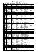
Page 20: ...COLPO PARE COUPS SHOCK ABSORBER STOßFäNGER PARACHOQUES 14 3210342 TUBO PEDALE TUBE PéDALE PEDAL PIPE ROHR PEDAL TUBO DEL PEDAL 15 3210283 GRUPPO TESTA ENDOTERMICA GROUPE DE TêTE ENDOTHERMIQUE ENDOTHERMIC HEAD UNIT ENDOTHERME BAUGRUPPE KOPF GRUPO CABEZAL ENDOTéRMICO 16 3210407 SUPPORTO SUPPORT SUPPORT UNTERLAGE SOPORTE 17 2223920 DADO AUTOBLOCCANTE ECROU DE SURETE SELF LOCKING NUT SELBSTSICHERNDE M...

Page 21: ...W SCHRAUBE TORNILLO M8X30 Z 60 3210189 DADO AUTOBLOCCANTE ECROU DE SURETE SELF LOCKING NUT SELBSTSICHERNDE MUTTER TUERCA AUTOBLOCANTE M 20 61 3210417 PORTAGOMMA EMBOUT FILITé POUR TUYAU HOOSE JOINT GUMMIHAL TERUNGSANSCHLU SS CONEXIóN DE TUBO 62 2204655 SUPPORTO SUPPORT SUPPORT SUPORTE 63 3210160 PULEGGIA POULIE PULLEY RIEMENSCHEIBE POLEA 64 3210346 TAPPO BOUCHON PLUG STOFFEN TAPON 100x50x3 65 3210...

Page 22: ...CHUTZHAU BE CÁRTER EXTERIOR CORREAS 4 3210330 CINGHIA COURROIE BELT RIEMEN CORREA 5 3210159 PULEGGIA POULIE PULLEY RIEMENSCHEIBE POLEA 6 2224190 ROSETTA RONDELLE WASHER UNTERLEGSCHEIBE ARANDELA 8X32 Z 7 2222076 VITE VIS BOLT SCHRAUBE TORNILLO M8X25 Z 8 2222176 VITE VIS BOLT SCHRAUBE TORNILLO M8X50 Z 9 2222004 VITE VIS BOLT SCHRAUBE TORNILLO M8X35 Z 10 2224140 ROSETTA RONDELLE WASHER UNTERLEGSCHEIB...

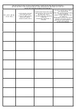
Page 23: ... D INSTALLATION PLACE OF INSTALLATION INSTALLATIONSORT LUGAR DE INSTALACIÓN VERIFICA PARTI DELLA MACCHINA ESSAIS PARTIES DE LA MACHINE MACHINE PART TESTS ABNAHME DER MASCHINENKOM PONENTEN PRUEBA DEL PARTES DE LA MÁQUINA RISULTATI ANNOTAZIONI E FIRMA DEL COMPILATORE RÉSULTATS ANNOTATIONS ET SIGNA TURE DU PRÉPOSÉ RESULTS NOTES AND SIGNATURE OF COMPILER ERGEBNISSE NOTIZEN UND UNTER SCHRIFT DES DUSFÜL...

Page 24: ... D INSTALLATION PLACE OF INSTALLATION INSTALLATIONSORT LUGAR DE INSTALACIÓN VERIFICA PARTI DELLA MACCHINA ESSAIS PARTIES DE LA MACHINE MACHINE PART TESTS ABNAHME DER MASCHINENKOM PONENTEN PRUEBA DEL PARTES DE LA MÁQUINA RISULTATI ANNOTAZIONI E FIRMA DEL COMPILATORE RÉSULTATS ANNOTATIONS ET SIGNA TURE DU PRÉPOSÉ RESULTS NOTES AND SIGNATURE OF COMPILER ERGEBNISSE NOTIZEN UND UNTER SCHRIFT DES DUSFÜL...

Page 25: ...ication tous les transferts vers et de notre centre assistance pour des réparations chez le client seront chargé au client Les réparations en garantie même s elles sont effectuées chez un des nos centre assistance autorisé il faut que soient approuvées par les techniciens du Service Assistance de Imer International Spa pour autoriser la réparation La garantie n est pas approuvé dans les cas suivan...

Page 26: ...chmiermittel verursachten Schäden bei durch eine nicht sachgerechte Schaltanlage durch Störungen im Versorgungsnetz oder durch nicht den Anweisungen in den Gebrauchs und Wartungsanleitungen entsprechenden Anschlüsse verursachten Schäden an den Elektrokomponenten Etwaige Streitfragen fallen unter die Zuständigkeit des Gerichtshofs Siena Außenstelle Poggibonsi Italien CONDICIONES DE GARANTIA El serv...

Page 27: ... der EG Richtlinie 2006 42 EG und 2000 14 EG mit dem entsprachenden Rechtserl zur Umsetzung der Richtline ins nationale Recht Corresponde a las exigencias bàsicas de le directive 2006 42 CE y 2000 14 CE y la corrispondiente transposiciòn a la nacional E conforme alle condizioni delle seguenti altre direttive Est conforme aux dispositions des Directives suivantes Complies with the provisions of the...

Page 28: ......
Reviews: