background image

2

Hinweise für den sicheren Gebrauch

Dieses Gerät entspricht der Richtlinie für elektro-
magnetische Verträglichkeit 89/336/EWG und der
Niederspannungsrichtlinie 73/23/EWG.

Beachten Sie auch unbedingt die folgenden Punkte:

Das Gerät ist nur zur Verwendung im Innenbe-
reich geeignet. Schützen Sie es vor Tropf- und
Spritzwasser, hoher Luftfeuchtigkeit und Hitze
(zulässiger Einsatztemperaturbereich 0 – 40 °C).

Stellen Sie keine mit Flüssigkeit gefüllten Gefäße,
z. B. Trinkgläser, auf das Gerät.

Nehmen Sie das Gerät nicht in Betrieb bzw. ziehen
Sie sofort den Netzstecker aus der Steckdose:
1. wenn sichtbare Schäden am Gerät oder an der

Netzanschlussleitung vorhanden sind,

2. wenn nach einem Sturz oder Ähnlichem der

Verdacht auf einen Defekt besteht,

3. wenn Funktionsstörungen auftreten.
Lassen Sie das Gerät in jedem Fall in einer Fach-
werkstatt reparieren.

Eine beschädigte Netzanschlussleitung darf nur
durch den Hersteller oder eine autorisierte Fach-
werkstatt ersetzt werden.

Ziehen Sie den Netzstecker nie am Kabel aus der
Steckdose, fassen Sie immer am Stecker an.

Verwenden Sie für die Reinigung nur ein trockenes,
weiches Tuch, niemals Wasser oder Chemikalien.

Wird das Gerät zweckentfremdet, nicht richtig an-
geschlossen, falsch bedient oder nicht fachgerecht
repariert, kann keine Haftung für daraus resultie-
rende Sach- oder Personenschäden und keine
Garantie für das Gerät übernommen werden.

Soll das Gerät endgültig aus dem Betrieb genom-
men werden, übergeben Sie es zur umweltge-
rechten Entsorgung einem örtlichen Recycling-
betrieb.

3

Einsatzmöglichkeiten und
Funktionseigenschaften

Das Lichtsteuerpult DMX-1440 ist speziell für den
Einsatz in professionellen Beleuchtungsanlagen auf
Bühnen oder in Diskotheken konzipiert. Lichteffekt-
geräte mit einem DMX 512-Eingang, z. B. Dimmer,
Scanner, Moving Heads usw., lassen sich über das
Pult steuern. Dazu stehen 96 Steuerkanäle zur Ver-
fügung, die sich über 12 Schieberegler bedienen
lassen.

DMX ist die Abkürzung für Digital  Multipleund

bedeutet digitale Steuerung von mehreren Geräten
über eine Leitung.

– Die 96 Steuerkanäle lassen sich den DMX-

Adressen 1 – 144 frei zuordnen. Daher kann die
Reihenfolge der Funktionen verschiedener DMX-
Geräte vereinheitlicht werden, was die Bedie-
nung erheblich erleichtert. Als Einstellhilfe lassen
sich alle Steuerkanäle gleichzeitig per Tasten-
druck auf Null zurücksetzen.

– Für die Ausgabewerte der 144 DMX-Adressen ist

eine Invertierung einstellbar. (Der Ausgabewert ist
0, wenn der zugeordnete Steuerkanal auf 255 ein-
gestellt wurde und umgekehrt.) Dadurch lassen
sich z. B. Bewegungsrichtungen korrigieren, wenn
ein DMX-Gerät seitenverkehrt montiert wurde.

Werden zwei Adressen zur Bewegungssteue-

rung demselben Steuerkanal zugeordnet und der
Ausgabewert für einer der Adressen invertiert,
lassen sich z. B. zwei Scanner synchron spiegel-
symmetrisch bewegen.

– Die 96 Steuerkanäle sind in 8 Gruppen (Control

Channel Pages) zu je 12 Kanälen zusammenge-
fasst. Die Werte sind einzeln oder gruppenüber-
greifend mit den Schiebereglern einstellbar. Der
eingestellte Wert wird als Dezimalwert und als

Prozentwert angezeigt. Bei Kanälen, die durch
den Master-Regler beeinflusst werden, wird
zusätzlich der tatsächliche Ausgabewert an-
gezeigt.

– Über die Flash-Tasten kann ein Steuerkanal auf

Maximum gestellt werden. Über die Taste FULL
ON lassen sich alle Steuerkanäle gleichzeitig auf
Maximum einstellen.

Es können auch Steuerkanäle in 5 verschie-

nenen Flash-Gruppen beliebig zusammenge-
stellt werden. Diese lassen sich dann (auch in
Kombination) über die 5 linken Flash-Tasten auf
den Maximalwert schalten. Die Flash-Funktion ist
für jeden Steuerkanal individuell abschaltbar.

– Über die BLACKOUT-Taste können alle Steuer-

kanäle gleichzeitig auf Minimum geschaltet wer-
den. Der Blackout-Zustand wird durch eine LED
angezeigt. Durch erneutes Drücken der Taste
wird zu den vorherigen Kanalwerten zurückge-
kehrt. Diese Funktion ist für jeden Steuerkanal
individuell abschaltbar.

– Über den Masterregler können die Werte aller

Steuerkanäle gemeinsam verringert werden.
Diese Funktion ist für jeden Steuerkanal individu-
ell abschaltbar.

– Mit dem Steuerhebel lassen sich die Steuer-

kanalpaare 1/2 und 7/8 jeder Kanalgruppe alter-
nativ zu den Schiebereglern steuern.

– Die eingestellten Werte können in 240 Szenen

(12 Szenen in 20 Banken) nichtflüchtig gespei-
chert werden.

– Zwischen den Szenen kann zeitgesteuert (0,1 bis

25,4 s) mit herunterzählender Restzeitanzeige
oder manuell übergeblendet werden. Die Über-
blendung mit vom Steuerpult berechneten Zwi-
schenwerten kann für jeden Steuerkanal ge-
trennt abgeschaltet werden.

– Die 240 gespeicherten Szenen können in 60

Sequenzen kombiniert werden. Es gibt 2 Se-
quenztypen: Sequenzen bei denen zu jedem der
maximal 60 Schritte eine individuelle Überblend-
zeit programmiert wird und Sequenzen mit maxi-

Achtung! Das Gerät wird mit lebensgefährlicher

Netzspannung (230 V~) versorgt. Neh-
men Sie deshalb niemals selbst Ein-
griffe im Gerät vor. Durch unsachge-
mäßes Vorgehen besteht die Gefahr
eines elektrischen Schlages. Außerdem
erlischt beim Öffnen des Gerätes jegli-
cher Garantieanspruch.

2

Safety Notes

This unit corresponds to the directive 89/336/EEC
for electromagnetic compatibility and to the low volt-
age directive 73/23/EEC.

It is essential to observe the following items:

The unit is suitable for indoor use only. Protect it
against dripping water and splash water, high air
humidity, and heat (admissible ambient tempera-
ture range 0 – 40 °C).

Do not place any vessels filled with liquid, e. g.
drinking glasses, on the unit.

Do not set the unit into operation, and immediately
disconnect the mains plug from the mains socket if
1. there is visible damage to the unit or to the

mains cable,

2. a defect might have occurred after a drop or

similar accident,

3. there are malfunctions.

The unit must in any case be repaired by skilled
personnel.

A damaged mains cable must only be replaced by
the manufacturer or by authorized, skilled personnel.

Never pull the mains cable to disconnect the mains
plug from the mains socket, always seize the plug.

For cleaning only use a dry, soft cloth, by no
means chemicals or water.

No guarantee claims for the unit and no liability for
any resulting personal damage or material dam-
age will be accepted if the unit is used for pur-
poses other than originally intended, if it is not cor-
rectly connected or operated, or not repaired in an
expert way.

If the unit is to be put out of operation definitively,

take it to a local recycling plant for disposal which
is not harmful to the environment.

Important for U. K. Customers!
The wires in this mains lead are coloured in
accordance with the following code:
blue = neutral
brown = live
As the colours of the wires in the mains lead of this
appliance may not correspond with the coloured
markings identifying the terminals in your plug,
proceed as follows:
1. The wire which is coloured blue must be con-

nected to the terminal in the plug which is
marked with the letter or coloured black.

2. The wire which is coloured brown must be con-

nected to the terminal which is marked with the
letter or coloured red.

3

Applications and Characteristics of
Functions

The controller DMX-1440 has especially been de-
signed for applications in professional lighting sys-
tems on stage or in discothèques. Light effect units
with a DMX512 input, e. g. dimmers, scanners,
moving heads, etc. can be controlled via this unit.
For this purpose 96 control channels are available
which can be operated via 12 sliding controls.

DMX is the abbreviation of Digital  Multipleand

means digital control of several units via a single line.
– The 96 control channels can be assigned as

desired to the DMX addresses 1 – 144. There-
fore, the order of the functions of different DMX
units can be unified which facilitates the opera-
tion considerably. As an adjusting aid it is possi-
ble to reset all control channels to zero simulta-
neously by pressing one key.

– For the output values of the 144 DMX addresses,

an inversion can be adjusted. (The output value
is 0 if the assigned control channel has been
adjusted to 255 and vice versa.) Thus, it is possi-
ble to correct e. g. moving directions if a DMX unit
has been mounted in a side-inverted way.

If two addresses for the motion control are

assigned to the same control channel and the
output value for one of the addresses is inverted,
it is possible e. g. to move two scanners synchro-
nously in a mirror symmetry.

– The 96 control channels are combined in 8

groups (Control Channel Pages) of 12 channels
each. The values can be adjusted individually or
for several groups with the sliding controls. The
adjusted value is indicated as a decimal value
and as a per cent value. For channels which are
influenced by the master fader, the actual output
value is indicated additionally.

– A control channel can be set to maximum via the

flash buttons. Via the button FULL ON all control
channels can be set to maximum simultaneously.

It is also possible to compile control channels

in 5 different flash groups as desired. These can
be set (also in combination) to the maximum
value via the 5 left flash buttons. The flash func-
tion can individually be switched off for each con-
trol channel.

– Via the BLACKOUT button all control channels

can be set to minimum simultaneously. The
blackout state is indicated by an LED. By press-
ing the button again, the unit reverses to the pre-
vious channel values. This function can individu-
ally be switched off for each control channel.

– Via the master fader the values of all control

channels may be reduced in common. This func-
tion can individually be switched off for each con-
trol channel.

– With the control lever it is possible to control the

control channel pairs 1/2 and 7/8 of each chan-
nel group alternatively to the sliding controls.

– The adjusted values can be memorized in 240

scenes (12 scenes in 20 banks) in a non-volatile
way.

– Between the scenes, it is possible to crossfade

time-controlled (0.1 to 25.4 s) with the remaining
time display counting downwards or to crossfade
manually. The crossfading with interim values

Attention! The unit is supplied with hazardous

mains voltage (230 V~). Leave servic-
ing to skilled personnel only. Inexpert
handling may cause an electric shock
hazard. Furthermore, any guarantee
claim will expire if the power supply unit
or the DMX controller has been opened.

6

GB

D

A

CH

Summary of Contents for DMX-1440

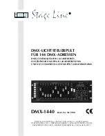
Page 1: ...KSAANWIJZING MANUAL DE INSTRUCCIONES SIKKERHEDSOPLYSNINGER SÄKERHETSFÖRESKRIFTER TURVALLISUUDESTA DMX LICHTSTEUERPULT FÜR 144 DMX ADRESSEN DMX CONTROLLER FOR 144 ADDRESSES CONTRÔLEUR DMX POUR 144 ADRESSES DMX UNITÀ DI COMANDO LUCE DMX PER 144 INDIRIZZI DMX DMX 1440 Best Nr 38 1980 ...

Page 2: ... instalación Tenemos de agradecerle el haber adquirido un aparato img Stage Line y le deseamos un agradable uso Este manual quiere ayudarle a conocer las multiples facetas de este aparato La observación de las instrucciones evita operaciones erróneas y protege Vd y vuestro apa rato contra todo daño posible por cualquier uso inade cuado La versión española se encuentra en las páginas 36 51 Förskrif...

Page 3: ... 29 30 31 32 SR 103DMX SR 105DMX MIN MAX MIN MAN MAX POWER MIC HOLD C F TIME AUDIO SENS TAP SPEED DELETE INSERT ESC SETUP SEQUENCE STORE PRG BANK AUDIO FULL ON BLACKOUT RUN PRG 1 2 7 8 MANUAL CROSSFADE MASTER LEVEL HOLD CROSSFADE CTRL CHANNEL PAGE SCENE NUMERICAL INPUT 1 2 3 4 5 6 7 8 9 0 NO YES 1 12 13 24 25 36 37 48 49 60 61 72 73 84 85 96 FL CH SH VAL U N I V E R S A L D M X C O N T R O L L E R...

Page 4: ... Überblend zeit zwischen zwei Szenen 0 25 4 s bei Rechtsanschlag Position MAN mit dem Contents 1 Operating Elements and Connections 4 1 1 Front panel 4 1 2 Rear panel 5 2 Safety Notes 6 3 Applications and Characteristics of Functions 6 4 Setting into Operation 7 4 1 Setting up the unit 7 4 2 Connecting the units 7 4 3 Adjusting the DMX start addresses of the light effect units 7 4 4 Configuring co...

Page 5: ...es mit Line Ausgang 0 1 2 V um den Ab lauf einer Szenensequenz im Takt der Musik zu steuern beim Anschluss der Buchse wird das interne Mikrofon 4 abgeschaltet 9 Control AUDIO SENS to adjust the threshold in case of music controlled run of a scene sequence 10 Button FLASH MODE to select the functions of the flash buttons 12 Basic setting red LED FL CH lights up When keeping a flash button 12 presse...

Page 6: ...li cher Garantieanspruch 2 Safety Notes This unit corresponds to the directive 89 336 EEC for electromagnetic compatibility and to the low volt age directive 73 23 EEC It is essential to observe the following items The unit is suitable for indoor use only Protect it against dripping water and splash water high air humidity and heat admissible ambient tempera ture range 0 40 C Do not place any vess...

Page 7: ...scenes can be combined in 60 sequences There are 2 sequence types se quences for which an individual crossfading time is programmed for each of the maximum of 60 steps and sequences with the maximum of 120 steps with the same crossfading time for all steps In this case the crossfading time is adjusted with the control C F TIME during the reproduction The sequences can run manually or automati call...

Page 8: ...S 2 the display shows DMX Patch and it is possible to assign the DMX address es 1 144 to one control channel 1 96 each and to invert the output values The following values are preset Fig 5 Presetting 1 To change the presetting select the DMX ad dress DMX Patch Ch with the numerical keys 12 and 11 2 or via the numerical keys 1 0 by 3 digit direct input 2 Go to Ctrl Ch with the cursor key 23 and ass...

Page 9: ...with the cursor key Define with the button 12 YES or 11 NO whether the control channel is to react on the flash buttons 12 and the button FULL ON 28 i e when pressing these buttons the control channel is set to the maximum value or not The flash function is useful for channels con trolling the brightness the iris and if necessary also the gobos The flash function should always be switched off for ...

Page 10: ...die gewünschte Flash Gruppe gespei chert wurde diese Gruppe auf den Maximal wert schalten c Um wieder einzelne Steuerkanäle auf den Maximalwert schalten zu können die Taste FLASH MODE so oft betätigen bis die rote LED FL CH Flash Channel leuchtet d The control lever is especially provided for chan nels for motion control e g pan tilt for scanners or moving heads This should be considered when the ...

Page 11: ...ks im Display angezeigt z B Bk01 a entweder schrittweise mit den Cursor Tasten und 23 oder 5 4 2 Setting all control channels to the maxi mum value By keeping the button FULL ON 28 pressed it is possible to set all control channels to the maximum value for which the function Full Flash has not been switched off when configuring the channels chapter 4 4 2 5 5 Blackout function With the blackout fun...

Page 12: ...Hold Modus aktiviert und die LED HOLD CROSSFADE unter der Taste HOLD 3 leuchtet Zum Überblenden auf die vorgemerkte Szene die Taste HOLD drücken oder bei manueller Überblendung den Crossfader 16 zur anderen Endposition schieben 0 and 4 observe the lower lettering of the but tons 3 Press the button STORE PRG 22 Store Scene is indicated in the display 4 If required the adjustments of the control cha...

Page 13: ...uenzschritte mit der Taste zwischen den einzelnen Szenenan gaben die programmierte Überblendzeit ange 7 Scene Sequences From the scenes previously memorized up to 120 scenes can be compiled to a scene sequence in any desired order and memorized 60 different sequences can be memorized These may run manually time controlled or controlled by an audio signal in forward or backward direction 7 1 Reprog...

Page 14: ...indigkeit diesen Reg ler auf die gewünschte Taktzeit einstellen oder für eine genauere Eingabe die Taste TAP SPEED zweimal drücken Nach dem ersten Drücken leuchtet die gelbe Takt LED nach dem zweiten erlischt sie wieder Die Zeit zwischen den beiden Tastenbetätigungen bestimmt die Zeit bis zum nächsten Szenenwechsel Wird die Taste TAP 3 Enter the two digit bank number and the two digit scene number...

Page 15: ...odus in den Direkt Modus gewechselt werden die grüne LED RUN erlischt the first pressing the yellow rhythm LED lights up after the second pressing it is extinguished The time between the two actuations of the but ton defines the time until the next change of scene If the button TAP SPEED is pressed only once after approx 13 minutes of running this maximum time is automatically adjusted as the rhyt...

Page 16: ...S anpas sen 3 Überblendzeit ggf mit Regler C F TIME verrin gern 4 Zur Richtungsänderung Taste rückwärts oder vorwärts drücken manuell starten 1 Wenn die gewählte Sequenz nicht vom Typ CFT ist d h mit gespeicherten Überblendzei ten die Überblendzeit mit Regler C F TIME ein stellen 2 Taste vorwärts oder rückwärts drücken um je einen Schritt weiter zu schalten bei laufen der Überblendung wird beim er...

Page 17: ...IO IN or of the internal microphone 2 Match the sensitivity with control AUDIO SENS 3 If necessary reduce the crossfading time with control C F TIME 4 To change the direction press button back ward or forward Manual start 1 If the selected sequence is not of type CFT i e with memorized crossfading times adjust the crossfading time with control C F TIME 2 Press button forward or backward to advance...

Page 18: ...d pin 2 DMX signal pin 3 DMX signal pins 4 and 5 not connected Audio input 0 1 2 V 22 kΩ stereo 6 3 mm jack Music control via internal microphone or jack AUDIO IN DMX addresses to be assigned 001 144 Control channels 96 Scenes to be memorized 240 12 each in 20 memory banks Sequences to be memorized 60 with max 120 steps Crossfading time 0 25 4 s or manual crossfading with crossfader Display LCD al...

Page 19: ...31 N N N N N 031 V 32 Y Y Y Y N 032 33 N N N N N 033 34 N N N N N 034 35 N 035 36 N 036 3 Moving Head Moving Head Fokus Farbe Gobo gobo Gobo Rotation focus colour gobo rotation Prisma prism Primsa Rotation prism rotation Drehen pan Neigen tilt Geschwindigkeit speed Blende iris 7 N 037 N N 048 37 48 H 4 N 049 N N 060 49 60 H 5 N 061 N N 072 61 72 H 6 N 073 N N 084 73 84 H 7 N 085 N N 096 85 96 H 8 ...

Page 20: ...er la durée de transition entre deux scènes 0 25 4 s lorsqu il est sur la butée droite position MAN transition avec le potentiomètre à glissières MANUAL CROSSFADE 16 Indice 1 Elementi di comando e collegamenti 20 1 1 Pannello frontale 20 1 2 Pannello posteriore 21 2 Avvertenze di sicurezza 22 3 Possibilità d impiego e caratteristiche 22 4 Messa in funzione 23 4 1 Collocare l apparecchio 23 4 2 Col...

Page 21: ...0 1 2 V pour gérer le déroulement d une séquence de scènes selon le rythme de la musique lorsque la prise est connectée le micro interne 4 est déconnecté 8 Interruttore on off POWER 9 Regolatore AUDIO SENS per impostare la so glia di reazione nel caso di svolgimento coman dato dalla musica di una sequenza di scene 10 Tasto FLASH MODE per selezionare la funzione dei tasti Flash 12 impostazione base...

Page 22: ...ulation vous pourriez subir une décharge électri que En outre l ouverture de l appareil rend tout droit à la garantie caduque 2 Avvertenze di sicurezza Quest apparecchio è conforme alle direttive CE 89 336 CEE sulla compatibilità elettromagnetica e 73 23 CEE per apparecchi a bassa tensione Durante l uso si devono osservare assolutamente i seguenti punti Lo strumento è previsto solo per l uso all i...

Page 23: ...de configuration solvenza è uguale per tutti i passi e dove tale durata viene impostata durante la riproduzione con il regolatore C F TIME Le sequenze possono svolgersi manualmente o automaticamente in avanti o indietro Lo svolgi mento automatico può essere comandato da un timer o dalla musica Esiste la possibilità di inter vento manuale durante lo svolgimento p es per modificare la direzione 4 Me...

Page 24: ...display indica DMX Patch e ognuno degli indirizzi DMX 1 144 può essere assegnato ad un canale di comando 1 96 inoltre si possono invertire i valori di output L impostazione di default è Fig 5 Impostazione di default 1 Per modificare l impostazione di default selezio nare l indirizzo DMX DMX Patch Ch per mezzo dei tasti 12 e 11 2 oppure tramite impostazione diretta a tre cifre con i tasti numerici ...

Page 25: ... Pour activer enfoncez la touche STICK CON TROL ASSIGN 1 2 17 et ou 7 8 19 La LED cor respondante STICK CTRL 11 13 indique que le ramento rapido Per i canali per pilotare il movi mento la funzione di blackout dovrebbe sempre essere disattivata 5 Con il tasto cursor spostarsi sul parametro Full Flash Con il tasto 12 YES o 11 NO decidere se il canale di comando deve reagire ai tasti Flash 12 e al ta...

Page 26: ...és a Si la LED jaune FL GRP Flash group à côté de la touche FLASH MODE ne brille pas activez aussi souvent que nécessaire la tou che FLASH MODE N B a Con la leva di comando attivata i valori delle relative coppie di canali vengono accettati diret tamente senza prendere in considerazione gli ultimi valori di output e contrariamente all im postazione fatta per mezzo dei regolatori cursori b Dopo ave...

Page 27: ... qu une scène déjà mémorisée peut toujours être dimmée dans sa totalité Pour éviter une influence erronée de la scène à mémoriser poussez le réglage entière ment vers le haut sur le maximum 5 4 2 Portare tutti i canali di comando sul valore massimo Tenendo premuto il tasto FULL ON 28 tutti quei canali di comando possono essere portati sul valore massimo per i quali la funzione Full Flash non è sta...

Page 28: ...e hold est activé et la LED HOLD CROSSFADE sous la touche HOLD 3 brille Pour passer à la scène retenue enfoncez la touche HOLD ou pour une transition manuelle poussez le crossfader 16 vers l autre position de fin 28 I F B CH b premere il tasto BANK AUDIO 27 e quindi digitare direttamente il numero a due cifre per mezzo dei tasti numerici 2 p es per la banca 4 i tasti 0 e 4 osservare l indicazione ...

Page 29: ...uence pour laquelle une durée de transition est mémorisée à chaque palier lors du déroulement des paliers de 7 Sequenze di scene Delle scene memorizzate precedentemente si pos sono riunire e memorizzare 120 scene in qualsiasi ordine per creare una sequenza È possibile memo rizzare 60 sequenze che possono svolgersi manual mente comandate dal timer o da un segnale audio in avanti o indietro 7 1 Nuov...

Page 30: ...glage du potentiomètre SEQUENCER SPEED 5 Pour modifier la vitesse de déroulement des séquences réglez ce réglage sur la durée de rythme souhaitée ou pour une saisie plus pré cise enfoncez deux fois la touche TAP SPEED après la première pression la LED jaune de rythme brille après la seconde pression elle s é 3 Con i tasti numerici 2 digitare i numeri a due cifre di banca e di scena per il numero d...

Page 31: ...eut ensuite sélec tionner un autre numéro de séquence ou par une nouvelle pression sur la touche SEQUENCE passer du mode séquence au mode direct la LED verte RUN s éteint fra i due azionamenti del tasto determina il perio do fino al successivo cambio di scena Se il tasto TAP SPEED viene premuto una sola volta dopo 13 minuti ca questo periodo massimo è impo stato automaticamente come periodo per il...

Page 32: ...nsition si besoin avec le réglage C F TIME 4 Pour modifier la direction enfoncez la touche vers l arrière ou vers l avant Démarrage manuel 1 Si la séquence choisie n est pas du type CFT c est à dire avec durées de transition mémo risées réglez la durée de transition avec le réglage C F TIME 2 Enfoncez la touche vers l avant ou vers l arrière pour commuter respectivement un palier pour une transiti...

Page 33: ...io ridurre la durata di dissolvenza con il regolatore C F TIME Poti 4 Per cambiare la direzione premere i tasti indietro o in avanti Avvio manuale 1 Se la sequenza scelta non è del tipo CFT cioè con durata di dissolvenza memorizzata impostare la durata di dissolvenza con il regola tore C F TIME 2 Premere il tasto avanti o indietro per spostarsi ogni volta di un passo con una dissol venza in corso ...

Page 34: ...oli pin 1 massa pin 2 segnale DMX pin 3 segnale DMX pin 4 e 5 liberi Ingresso audio 0 1 2 V 22 kΩ stereo jack 6 3 mm Comando musica tramite microfono inter no o presa AUDIO IN Indirizzi DMX assegnabili 001 144 Canali di comando 96 Scene memorizzabili 240 n 12 in 20 ban che di memorie Sequenze memorizzabili 60 con 120 passi max Durata di dissolvenza 0 25 4 s o dissol venza manuale con crossfader Di...

Page 35: ...0 H 31 N N N N N 031 V 32 Y Y Y Y N 032 33 N N N N N 033 34 N N N N N 034 35 N 035 36 N 036 3 Lyre Moving Head Focus Couleur Gobo Gobo Rotation gobo Fuoco Colore Rotazione gobo Prisme Prisma Rotation prisme Rotazione prisma Pan rotation Ruotare Tilt inclinaison Inclinare Vitesse Velocità Diaphragme Diaframma 7 N 037 N N 048 37 48 H 4 N 049 N N 060 49 60 H 5 N 061 N N 072 61 72 H 6 N 073 N N 084 73...

Page 36: ...dad de desarrollo de una secuencia de escenas 6 Pantalla alfanumérica 7 Potenciómetro C F TIME para regular la dura ción de transición entre dos escenas 0 25 4 s cuando está en tope derecho posición MAN transición con el potenciómetro deslizante MANUAL CROSSFADE 16 36 E NL B Inhoudsopgave 1 Overzicht van de bedienings elementen en aansluitingen 36 1 1 Frontpaneel 36 1 2 Achterzijde 37 2 Veiligheid...

Page 37: ...gang 0 1 2 V om de 8 Interruptor POWER ON OFF 9 Potenciómetro AUDIO SENS para reglar el limite de activación en el caso de un desarrollo controlado por música de una secuencia de escenas 10 Tecla FLASH MODE para la selección de funcio nes de las teclas Flash 12 Reglaje de base el LED rojo FL CH brilla Cuando mantiene pulsada una tecla Flash 12 independientemente del potenciómetro MASTER LEVEL 15 e...

Page 38: ...l aparato podría en caso de mani pulación inadecuada sufrir una descarga eléctrica Además la apertura del aparato carece de todo tipo de garantía 38 E NL B weergave van een scènesequentie op het ritme van de muziek te sturen bij het aansluiten van de jack wordt de ingebouwde microfoon 4 uit geschakeld 2 Veiligheidsvoorschriften Dit apparaat is in overeenstemming met de EU richt lijn 89 336 EEG voo...

Page 39: ...ara cada uno de las 60 etapas como máximo y las secuencias con 120 etapas como máximo para las cuales la duración de transición para todas las etapas es idéntica y regulada durante la resti tución con el potenciómetro C F TIME Las secuencias pueden desfilar manualmente automáticamente hacia adelante o hacia atrás el desarrollo automático puede controlarse por música o el tiempo Una intervención ma...

Page 40: ...n Na de bevestiging van de vraag Output Options met de toets 12 YES 2 verschijnt de melding DMX Patch en kunt u de DMX adressen 1 144 elk aan een besturingskanaal 1 96 toewijzen en de uitvoerwaarde inverteren Standaard ingesteld is Fig 5 Voorinstelling 1 Om de voorinstelling te wijzigen selecteert u het DMX adres DMX Patch Ch met de cijfer toetsen 12 en 11 2 of door rechtstreekse invoer van drie c...

Page 41: ...o 11 NO seleccione si el canal de control debe reaccionar a las teclas Flash 12 y a la tecla FULL ON 28 es decir cuando estas teclas están activadas el canal de control está regulado en el valor máximo o no La función Flash es útil para los canales para el control de la luminosidad del diafragma o si necesario de los gobos Para los canales que controlan los movimientos y la activación de una reini...

Page 42: ...r canal de control en el valor máximo pulsar la tecla FLASH MODE tantas veces hasta que el LED rojo FL CH Flash Channel se ilumine 42 E NL B Opmerkingen a Bij geactiveerde besturingshendel worden de waarden voor de betreffende kanaalparen onge acht de laatste uitvoerwaarde onmiddellijk over genomen Dit is niet het geval bij het instellen met de schuifregelaars b Na het deactiveren van de besturing...

Page 43: ...4 2 Conmutación de todos los canales de con trol en el valor máximo Mientras la tecla FULL ON 28 está pulsada todos los canales de control pueden ser conmutados en el valor máximo para los cuales la función Full Flash no ha sido desactivada con la configuración de los canales capítulo 4 4 2 5 5 Función Blackout Con la función Blackout es posible por ejemplo oscurar completamente una escena de luz ...

Page 44: ... la tecla HOLD o para una transi ción manual pulse el crossfader 16 hacia la otra posición final 44 E NL B van de op te slagen scène zou ontstaan plaatst u deze regelaar helemaal naar boven in de maxi mumstand 2 Selecteer de geheugenbank de huidige bank wordt bovenaan links op het display weergege ven b v Bk01 a ofwel stapsgewijs met de cursortoetsen en 23 of b druk op de toets BANK AUDIO 27 en vo...

Page 45: ...de sequentiestappen met de toets tussen de afzonderlijke scènegege 7 Secuencias de escenas Es posible crear y memorizar hasta 120 escenas en el orden que desea a partir de escenas prealable mente memorizada Puede memorizar hasta 60 se cuencias diferentes Puede controlarlas manual mente según la duración o mediante una señal audio hacia delante o hacia atrás 7 1 Nueva programación o modificación de...

Page 46: ...lse dos veces la tecla TAP SPEED después de la primera presión el LED amarillo de ritmo se ilumina después de la se 46 E NL B vens de geprogrammeerde mengtijd weergege ven alvorens na nogmaals drukken op de toets naar de volgende stap wordt geschakeld Indien u alleen de mengtijd wilt wijzigen ga dan voort met bedieningsstap 5 3 Voer met de cijfertoetsen 2 het banknummer en het scènenummer in elk t...

Page 47: ...n de groene LED RUN gaat uit gunda presión se apaga La duración entre las dos activaciones de la tecla determina la dura ción hasta el próximo cambio de escena Si pulsa solo una vez la tecla TAP SPEED después de unos 13 minutos de desarrollo este tiempo máximo se regula automáticamente como dura ción de ritmo El LED de ritmo se apaga Consejo si el reglaje vía la tecla TAP SPEED no parece funcionar...

Page 48: ...r meerdere keren op de toets ESC SETUP te drukken 48 NL B 8 Kort overzicht via de besturing Een scène instellen 1 Selecteer de besturingskanaalgroep en met de toetsen CTRL CHANNEL PAGE 1 12 tot 85 96 2 Stel de regelaar MASTER LEVEL in op de maxi mumwaarde 3 Stel de scène met de schuifregelaars in laatste waarde moet door de regelaar worden opge haald 4 Activeer eventueel de besturingshendel MOTION...

Page 49: ...on el potenciómetro AUDIO SENS 3 Disminuya la duración de transición si necesario con el potenciómetro C F TIME 4 Para modificar el sentido pulse la tecla hacia atrás o hacia delante Arranque manual 1 Si la secuencia elegida no es del tipo CFT es decir con duraciones de transición memoriza das regule la duración de transición con el potenciómetro C F TIME 2 Pulse la tecla hacia delante o hacia atr...

Page 50: ...ie en vijfpolig Pin 1 massa Pin 2 DMX signaal Pin 3 DMX signaal Pin 4 en 5 niet aan gesloten Audio ingang 0 1 2 V 22 kΩ stereo 6 3 mm jack Muzieksturing via een ingebouwde microfoon of jack AUDIO IN Toewijsbare DMX adressen 001 144 Besturingskanalen 96 Opslaanbare scènes 240 telkens 12 in 20 geheugenbanken Opslaanbare sequenties 60 max 120 stappen Mengtijd 0 25 4 sec of manu eel mengen met cross f...

Page 51: ... 31 N N N N N 031 V 32 Y Y Y Y N 032 33 N N N N N 033 34 N N N N N 034 35 N 035 36 N 036 3 Moving Head Cabeza Focus Kleur Gobo Gobo Gobo rotatie Foco Color Rotación gobo prisma Prisma prismarotatie Rotación prisma Draaien Pan rotación Kantelen Tilt inclinación Snelheid Velocidad Diafragma Diafragma 7 N 037 N N 048 37 48 H 4 N 049 N N 060 49 60 H 5 N 061 N N 072 61 72 H 6 N 073 N N 084 73 84 H 7 N ...

Page 52: ... eller net kablet 2 hvis der kan være opstået skade efter at enhe den er tabt eller lignende 3 hvis der forekommer fejlfunktion Enheden skal altid repareres af autoriseret per sonel Et beskadiget netkabel må kun repareres af pro ducenten eller af autoriseret personel Tag aldrig netstikket ud af stikkontakten ved at trække i kablet tag fat i selve stikket Til rengøring må kun benyttes en tør blød k...

Page 53: ...53 ...
Page 54: ...ash Funktion möglich Full On Flash function enable 07 08 09 10 11 12 DMX Adressenzuordnung DMX address assignment DMX patch DMX Adresse DMX address Ausgabe invers Output inverted DMX Adresse DMX address Ausgabe invers Output inverted DMX Adresse DMX address Ausgabe invers Output inverted DMX Gerät DMX unit 2 13 14 15 16 17 18 19 20 21 22 23 24 3 25 26 27 28 29 30 31 32 33 34 35 36 4 37 38 39 40 41...

Page 55: ...ash Funktion möglich Full On Flash function enable DMX Adressenzuordnung DMX address assignment DMX patch 55 56 57 58 59 60 DMX Gerät DMX unit 6 61 62 63 64 65 66 67 68 69 70 71 72 7 73 74 75 76 77 78 79 80 81 82 83 84 8 85 86 87 88 89 90 91 92 93 94 95 96 DMX Adresse DMX address Ausgabe invers Output inverted DMX Adresse DMX address Ausgabe invers Output inverted DMX Adresse DMX address Ausgabe i...

Page 56: ...y bank Szene Scene 2 2 3 4 3 5 Beschreibung Description 6 4 7 8 5 15 9 1 10 6 11 12 7 8 16 9 1 10 11 12 2 3 4 5 6 7 8 17 9 1 10 11 12 2 3 4 5 6 7 8 18 9 1 10 11 12 2 3 4 5 6 7 8 19 9 1 10 11 12 2 3 4 5 6 7 8 20 9 1 10 11 12 Speicherbank Memory bank Szene Scene 2 2 3 4 3 5 Beschreibung Description 6 4 7 8 5 08 9 1 10 6 11 12 7 8 09 9 1 10 11 12 2 3 4 5 6 7 8 10 9 1 10 11 12 2 3 4 5 6 7 8 11 9 1 10 ...

Page 57: ...Copyright by MONACOR INTERNATIONAL GmbH Co KG Bremen Germany All rights reserved A 0223 99 01 06 2004 ...

Reviews: