oder 11/NO wählen, ob der Steuerkanal auf die
Flash-Tasten (12) und die Taste FULL ON (28)
reagieren soll (d. h. beim Drücken dieser Tasten
wird der Steuerkanal auf den Maximalwert ge-
stellt) oder nicht.
Die Flash-Funktion ist sinnvoll bei Kanälen zur
Steuerung der Helligkeit, der Blende, ggf. auch
der Gobos. Bei Kanälen zur Bewegungssteue-
rung und zur Reset-Auslösung sollte die Flash-
Funktion immer ausgeschaltet werden.
6) Mit der Taste ESC/SETUP (21) oder
auf die
Eingabe einer neuen Steuerkanalnummer sprin-
gen. Die Bedienschritte für weitere Kanäle wie-
derholen oder zum Verlassen der Optionseinstel-
lungen die Taste ESC/SETUP erneut betätigen
(Anzeige: „Output Options? Y/N“). Um das
Menü zu verlassen, die Taste ESC/SETUP noch
einmal drücken.
4.4.3 Zurücksetzen sämtlicher Adressenzuord-
nungen und Steuerkanaloptionen
Alle vorgenommenen Adressenzuordnungen und
Steuerkanaloptionen lassen sich bei Bedarf auf die
Voreinstellungen (siehe Abb. 5 und Kap. 4.4.2 nach
1. Absatz) zurücksetzen.
1) Das Konfigurationsmenü mit der Taste ESC/
SETUP (21) aufrufen.
Anzeige: „Output Options? Y/N“.
2) Die Taste 11/NO (2) drücken.
Anzeige: „Control Options? Y/N“.
3) Die Taste 11/NO erneut drücken.
Anzeige „Reset All Opt’s? Y/N“.
4) Entweder zum Bestätigen die Taste 12/YES drü-
cken, Anzeige: „Reset All Opt’s? Sure ? ? ?
Y/N“ oder die Taste 11/NO drücken, wenn keine
Rücksetzung erfolgen soll.
5) Wird die Frage „Reset All Opt’s? Sure ? ? ?“ mit
der Taste 12 / YES bejaht, erfolgt die Rücksetzung.
Das Display zeigt wieder „Output Options? Y/ N“.
Jetzt können die Steuerkanäle neu konfiguriert
werden (Taste 12 / YES drücken) oder das Menü
kann mit der Taste ESC/SETUP verlassen werden.
5
Bedienung im Direkt-Modus
Das Steuerpult mit dem Schalter POWER (8) ein-
schalten. Das Display zeigt kurz „img Stage Line
DMX-1440“ und die Nummer der Software-Version.
Danach erscheint in der ersten Zeile „Bk01 01/01“.
Nach dem Einschalten ist immer die 1. Szene aus
der Speicherbank 1 aufgerufen. Deshalb sollte für
diese Szene eine geeignete Basisbeleuchtung ge-
speichert werden (Kap. 6.1).
5.1 Beleuchtungsszene einstellen
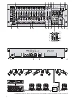
1) Mit den Tasten CONTROL CHANNEL PAGE (1)
die Gruppe wählen, in der die einzustellenden
Steuerkanäle liegen (1 – 12, 13 – 24, 25 – 36,
37 – 48, 49 – 60, 61 – 72, 73 – 84, 85 – 96).
Sollen in verschiedenen Gruppen liegende
Kanäle gleichzeitig auf denselben Wert eingestellt
werden, können auch mehrere Gruppen gewählt
werden. Dazu die entsprechenden Tasten gleich-
zeitig drücken. Die LEDs neben den Tasten zei-
gen die aktivierten Gruppen an.
2) Zur Grundeinstellung den Regler MASTER
LEVEL (15) ganz nach oben auf Maximum schie-
ben. Dann mit den grauen Schiebereglern (14)
die gewünschten Einstellungen vornehmen. Wird
ein Regler bewegt, so zeigt das Display (6) in der
unteren Zeile die Nummer des Steuerkanals,
z. B. „C15:“ und den momentanen Ausgabewert
als DMX-Wert und in Prozent (bezogen auf den
Maximalwert), z. B. „118 = 46 %“. Ist bei der Steu-
erkanalkonfiguration festgelegt worden, dass
dieser Kanal vom Regler MASTER LEVEL (15)
abhängig sein soll und steht der Regler MASTER
LEVEL nicht auf Maximum, wird zusätzlich noch
der resultierende Ausgabewert in Prozent ange-
zeigt (z. B. „
"
23 %“).
Wird einer der grauen Schieberegler erstmalig
nach dem Anwählen einer Steuerkanalgruppe
bewegt, reagiert der Ausgabewert nicht sofort auf
die Bewegung des Reglers. Der vom Display
angezeigte Ausgabewert muss erst mit dem Reg-
ler „abgeholt“ werden. Die Einstellung auf einen
neuen Wert wird dann wirksam, wenn der Regler
zuvor auf die Position geschoben wurde, die dem
angezeigten Ausgabewert entspricht. Sind meh-
rere Kanalgruppen gleichzeitig angewählt, muss
immer der Ausgabewert des Kanals mit der nied-
rigsten Nummer „abgeholt“ werden. Auf diese
Weise treten keine abrupten Sprünge der Ausga-
bewerte auf, wenn auf eine andere Steuerkanal-
gruppe oder Beleuchtungsszene umgeschaltet
wird.
3) Als Ausgangsposition können alle Steuerkanäle
auf den Wert Null gesetzt werden. Dazu folgende
Tasten nacheinander betätigen:
STORE/PRG (22)
DELETE (24)
STORE/PRG
Tipp Nach dem Einschalten des Gerätes alle
grauen Schieberegler nach unten auf Null
schieben. Dann den Steuerkanälen den
Wert Null zuweisen. Dadurch reagieren die
Ausgabewerte sofort beim Betätigen der
Schieberegler.
5.2 Bedienung des Steuerhebels
Vier Steuerkanäle jeder Kanalgruppe können alter-
nativ zu den Schiebereglern über den Steuerhebel
(18) eingestellt werden. Die beiden Kanalpaare 1 + 2
sowie 7 + 8 jeder Gruppe lassen sich unabhängig
voneinander aktivieren (Bewegung horizontal = 1.
oder 7. Kanal, vertikal = 2. oder 8. Kanal).
Zum Aktivieren die Taste STICK CONTROL
ASSIGN 1/2 (17) und/oder 7/8 (19) drücken. Die
zugehörige LED STICK CTRL (11, 13) zeigt, dass
der Steuerhebel für die entsprechenden Kanäle der
gewählten Gruppe (n) aktiv ist. Zur Deaktivierung
die Taste nochmals drücken.
Hinweise
a) Bei aktiviertem Steuerhebel werden die Werte für
die entsprechenden Kanalpaare, im Gegensatz
zu der Einstellung über die Schieberegler, unge-
achtet der letzten Ausgabewerte unmittelbar
übernommen.
5) Go the parameter “Full/Flash:” with the cursor
key
. Define with the button 12/YES or 11/NO
whether the control channel is to react on the
flash buttons (12) and the button FULL ON (28)
[i. e. when pressing these buttons, the control
channel is set to the maximum value] or not.
The flash function is useful for channels con-
trolling the brightness, the iris, and, if necessary,
also the gobos. The flash function should always
be switched off for channels which control the
motion and release the reset.
6) With the button ESC/SETUP (21) or
go to the
input of a new control channel number. Repeat
the operating steps for further channels or
actuate the button ESC/SETUP again to exit the
adjustments of the options (indication: “Output
Options? Y/N”). To exit the menu, press the key
ESC/SETUP once again.
4.4.3 Reset of all address assignments and con-
trol channel options
All address assignments and control channel options
made can be reset to the presettings, if necessary
(see fig. 5 and chap. 4.4.2 after the first paragraph).
1) Call the configuration menu with the button ESC/
SETUP (21).
Indication: “Output Options? Y/N”.
2) Press the button 11/NO (2).
Indication: “Control Options? Y/N”.
3) Press the button 11/NO again.
Indication “Reset All Opt’s? Y/N”.
4) Either press the button 12/YES, indication:
“Reset All Opt’s?
Sure ? ? ? Y/N” to confirm or
the button 11/NO if no reset is to be made.
5) If the question “Reset All Opt’s?
Sure ? ? ?” is
affirmed with the button 12/YES, the unit will be
reset. The display indicates again “Output Op-
tions?
Y/N”. Now the control channels can be
reconfigured (press the button 12/YES) or the
menu can be exited with the button ESC/SETUP.
5
Operation in the Direct Mode
Switch on the controller with the POWER switch (8).
The display shortly indicates “img Stage Line DMX-
1440” and the number of the software version. Then
“Bk01 01/01” is displayed in the first line. After
switching-on, always the first scene from the memory
bank 1 is called. Therefore, a suitable basic illumina-
tion should be memorized for this scene (chap. 6.1).
5.1 Adjusting an illumination scene
1) With the buttons CONTROL CHANNEL PAGE (1)
select the group in which the control channels to
be adjusted are located (1 – 12, 13 – 24, 25 – 36,
37 – 48, 49 – 60, 61 – 72, 73 – 84, 85 – 96).
For adjusting channels located in different
groups to the same value at the same time, it is
also possible to select several groups. For this
purpose press the corresponding buttons at the
same time. The LEDs next to the buttons show
the activated groups.
2) For the basic adjustment slide the fader MAS-
TER LEVEL (15) fully upwards to the maximum
position. Then make the desired adjustments
with the grey sliding controls (14). If a control is
moved, the display (6) shows the number of the
control channel in the lower line, e. g. “C15:” and
the current output value as a DMX value and in
per cent (referred to the maximum value), e. g.
“118 = 46 %”. If it has been defined for the confi-
guration of the control channel that this channel
is to depend on the fader MASTER LEVEL (15)
and if the fader MASTER LEVEL is not in the
maximum position, the resulting output value is
additionally indicated in per cent (e. g. “
"
23 %”).
If one of the grey sliding controls is moved for
the first time after selecting a control channel
group, the output value does not react immedi-
ately on the movement of the sliding control. The
output value indicated by the display must first be
“fetched” with the fader. The adjustment to a new
value is effective if the fader has previously been
slid to the position which corresponds to the out-
put value indicated. If several channel groups are
selected at the same time, always the output
value of the channel with the lowest number must
be “fetched”. This way no abrupt jumps of the out-
put values occur when the unit switches to an-
other control channel group or illumination scene.
3) All control channels can be set to the value zero
as an initial position. For this purpose actuate the
following buttons one after the other:
STORE/PRG (22)
DELETE (24)
STORE/PRG
Note After switching on the unit, slide all grey
sliding controls downwards to zero. Then
assign the value zero to the control chan-
nels. Thus, the output values immediately
react when actuating the sliding controls.
5.2 Operating the control lever
Four control channels of each channel group may
be adjusted alternatively to the sliding controls via
the control lever (18). The two channel pairs 1 + 2
and 7 + 8 of each group can be activated independ-
ently of each other (movement horizontal = 1st or
7th channel, vertical = 2nd or 8th channel).
To activate, press the button STICK CONTROL
ASSIGN 1/2 (17) and/or 7/8 (19). The respective
LED STICK CTRL (11, 13) shows that the control
lever for the corresponding channels of the selected
group(s) is active. To deactivate, press the button
once again.
Notes
a) With activated control lever, contrary to the
adjustment via the sliding controls, the values for
the corresponding channel pairs are immediately
taken over, irrespective of the last output values.
b) A fine adjustment of the channels can be made
after the deactivation of the control lever via the
sliding controls.
c) When calling a scene (chapter 6.2), the control
lever is automatically deactivated.
9
GB
D
A
CH
Summary of Contents for DMX-1440
Page 53: ...53 ...

