background image

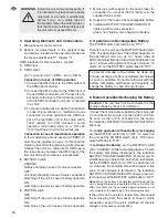
4 Operating Elements and Connections

1

Microphone for music control

2

Buttons for adjustments in the system menu
and display to indicate the operating mode and
the menu adjustments 

chapter 7.1

DMX interface (XLR connections, 3-pole):

3

DMX input

4

DMX output

pin 1 = ground, pin 2 = DMX-, pin 3 = DMX+

Connection in case of DMX operation

1. Connect the DMX input to the DMX output of

the DMX light controller.

2. Connect the DMX output to the DMX input of

the next DMX-controlled unit. Connect its out-
put again to the input of the following unit etc.,
until all DMX-controlled units are connected
in a chain.

3. To prevent interference in signal transmission

in case of long cables or a multitude of units
connected in series, terminate the DMX out-
put of the last DMX unit in the chain with a
120 Ω resistor (> 0.3 W): Connect a corre-
sponding terminating plug (e. g. DLT-123
from “img Stage Line”) to the output jack.

Connection in case of master/slave operation

In the master/slave mode several LITEBOX-10
units may be operated in sync. In this case the
master unit controls the remaining units (slaves).
Connect the units in a chain like for DMX opera-
tion (see above), however, the DMX input of the
first unit of the chain remains unconnected.

5

BATTERY switch
CHARGE:
battery charging in case of mains connection
OFF:
no battery charging in case of mains connection/
switching off the unit in case of battery operation
ON:
switching on the unit in case of battery operation

6

POWER switch
OFF:
switching off the unit in case of mains operation
ON:
switching on the unit in case of mains operation

7

Mains jack (with support for the mains fuse) for
connection to a socket (230 V~/ 50 Hz) via the
supplied mains cable

8

Support for the fuse of the rechargeable battery

9

Indication BATTERY CHARGE INDICATOR,
lights up with mains connection
green: no charging, red: charging of battery

5 Operation via Rechargeable Battery

The POWER switch (6) remains on “OFF”.

To switch on the unit, set the BATTERY switch (5) to
“ON”. The operating time of the battery depends on
the operating mode, e. g. up to 7 hours when all
LEDs constantly light up at maximum brightness and
up to 16 hours with automatic change of colours. To
switch off, set the BATTERY switch back to “OFF”.

6 Mains Operation/Recharging the Battery

Connect the mains cable supplied to the mains jack
(7) and the mains plug to a socket (230 V~/ 50 Hz).
As soon as the unit is connected to the mains,
the indication BATTERY CHARGE INDICATOR (9)
lights up.

For 

mains operation without battery recharging

set the BATTERY switch (5) to “OFF”. To switch on
the unit, set the POWER switch (6) to “ON” and to
switch off back to “OFF”.

To 

recharge the battery

, set the BATTERY switch

(5) to “CHARGE”. While recharging (approx. 5 h with
the battery completely discharged), the indication
BATTERY CHARGE INDICATOR (9) shows red. To
simultaneously operate the unit while recharging,
set the POWER switch (6) to “ON” to switch the unit
on. However, the charging time will be longer in this
case. Once charging is terminated, the indication
BATTERY CHARGE INDICATOR shows green. Af-
ter charging, set the BATTERY switch back to “OFF”.

Note:

When the battery is completely discharged and the

unit is being charged and operated at the same time, the
LEDs may flicker as the complete operating power is not
yet available at the beginning of the charging process.

If the unit is not in use for a longer time, disconnect
the mains plug from the socket. In case of mains
connection, even if the unit is switched off, there is
always a low power consumption.

Caution:

The unit must not be connected to the

mains voltage by means of a dimmer!

To prevent damage to the battery by deep dis-
charge, recharge a battery completely discharged
as soon as possible. Do not store the unit with the
battery completely discharged and regularly re -
charge the battery in case of long storage.

WARNING

Install the unit safely and expertly. If
it is installed at a place where people
may walk or sit under it, additionally
secure it (e. g. via a safety rope on
the bracket; fasten the safety rope so
that the maximum falling distance of
the unit will not exceed 20 cm).

10

GB

Summary of Contents for LITEBOX-10

Page 1: ...ACCUMULATEUR PROIETTORE DMX A LED CON BATTERIA RICARICABILE LITEBOX 10 Bestellnummer 38 5970 BEDIENUNGSANLEITUNG INSTRUCTION MANUAL MODE D EMPLOI ISTRUZIONI PER L USO MANUAL DE INSTRUCCIONES VEILIGHE...

Page 2: ...2...

Page 3: ...D A CH GB Innan du sl r p enheten Vi nskar dig mycket gl dje med din nya img Stage Line produkt L s igenom s kerhetsf re skrifterna innan enheten tas i bruk f r att undvika skador till f ljd av felak...

Page 4: ...in eine Fachwerkstatt G Ziehen Sie den Netzstecker nie am Kabel aus der Steckdose fassen Sie immer am Stecker an G Eine durchgeschmolzene Sicherung nur durch eine gleichen Typs ersetzen G Wird das Ger...

Page 5: ...vorgang rot Akku wird geladen 5 Akkubetrieb Der Schalter POWER 6 verbleibt auf OFF Zum Einschalten des Ger ts den Schalter BAT TERY 5 auf ON stellen Die Akku Betriebszeit h ngt vom Betriebsmodus ab z...

Page 6: ...er die vier Tasten 2 bedient 1 Das Men mit der Taste MENU aufrufen 2 Den gew nschten Men punkt mit der Taste UP oder MENU oder DOWN anw hlen und mit der Taste ENTER aufrufen 3 Mit der Taste UP oder DO...

Page 7: ...en gr nen und gelben LEDs separat einstellen und damit der gew nschte Farbton einer Mischfarbe Die hier eingestellten Werte gelten nur f r das jeweilige Ger t So k nnen bei Master Slave Betrieb f r je...

Page 8: ...55 Grundhelligkeit der roten LEDs 0 100 2 0 255 Grundhelligkeit der gr nen LEDs 0 100 3 0 255 Grundhelligkeit der blauen LEDs 0 100 4 0 255 Grundhelligkeit der gelben LEDs 0 100 5 0 255 Gesamthelligke...

Page 9: ...mage will be accepted if the unit is used for other purposes than originally intended if it is not safely mounted not correctly operated or not repaired in an expert way G Important for U K Customers...

Page 10: ...the BATTERY switch 5 to ON The operating time of the battery depends on the operating mode e g up to 7 hours when all LEDs constantly light up at maximum brightness and up to 16 hours with automatic...

Page 11: ...ents The menu is operated via the four buttons 2 1 Call the menu with the button MENU 2 Select the desired menu item with the button UP or MENU or DOWN and call it with the button ENTER 3 Select the d...

Page 12: ...een and yellow LEDs can separately be adjusted and thus the desired shade of colour of a mixed colour The values adjusted here only apply to the respective unit In case of master slave mode different...

Page 13: ...nstruction manual may be reproduced in any form or by any means for any commercial use 8 CHANNEL MODE Channel DMX value Function 1 0 255 basic brightness of the red LEDs 0 100 2 0 255 basic brightness...

Page 14: ...branchez jamais l appareil en tirant sur le cordon secteur retirez toujours le cordon sec teur en tirant la fiche G Tout fusible fondu doit imp rativement tre rem plac par un fusible de m me type G No...

Page 15: ...accumulateur en charge 5 Fonctionnement accumulateur L interrupteur POWER 6 reste sur OFF Pour allumer l appareil mettez l interrupteur BAT TERY 5 sur ON La dur e de fonctionnement sur accumulateur d...

Page 16: ...2 1 Appelez le menu avec la touche MENU 2 S lectionnez le point du menu voulu avec la touche UP ou MENU ou DOWN et appelez avec la touche ENTER 3 Avec la touche UP ou DOWN s lectionnez le r glage voul...

Page 17: ...par ment la luminosit des LEDs rouges bleus vertes et jaunes et ainsi la tonalit voulue d une couleur de mixage Les valeurs r gl es ne valent que pour un seul appareil Ainsi en mode master slave on p...

Page 18: ...ht de MONACOR INTERNATIONAL GmbH Co KG Toute reproduction m me partielle des fins commerciales est interdite MODE 8 CANAUX Canal Valeur DMX Fonction 1 0 255 luminosit de base des LEDs rouges 0 100 2 0...

Page 19: ...o d uso improprio di montaggio non sicuro d impiego scorretto o di riparazione non a regola d arte dell apparecchio non si assume nessuna responsabilit per eventuali danni con sequenziali a persone o...

Page 20: ...su OFF Per accendere l apparecchio mettere l interruttore BATTERY 5 su ON La durata della batteria dipende dal modo di funzionamento p es fino a 7 ore se tutti i LED sono accesi costantemente con la m...

Page 21: ...omandato tramite i quattro tasti 2 1 Chiamare il men con il tasto MENU 2 Scegliere la voce desiderata del men con il tasto UP o MENU o DOWN e chiamarla con il tasto ENTER 3 Con il tasto UP o DOWN sceg...

Page 22: ...la lumi nosit dei LED rossi blu verdi e gialli e quindi la tonalit cromatica di un colore miscelato I valori indicati qui sono validi solo per il relativo apparecchio Con il funzionamento master slav...

Page 23: ...ualsiasi forma delle presenti istruzioni per l uso La riproduzione anche parziale per propri scopi commerciali vietata MODO A 8 CANALI Canale Valore DMX Funzione 1 0 255 Luminosit base dei LED rossi 0...

Page 24: ...empre un fusible fundido s lo por otro del mismo tipo G No podr reclamarse garant a o responsabilidad alguna por cualquier da o personal o material resultante si el aparato se utiliza para otros fines...

Page 25: ...uptor BAT TERY 5 en posici n ON El tiempo de funciona miento de la bater a depende del modo de funcio namiento p ej hasta 7 horas cuando todos los LEDs se iluminan constantemente y con el brillo m xim...

Page 26: ...cuatro botones 2 1 Abra el men con el bot n MENU 2 Seleccione el objeto del men con el bot n UP o MENU o DOWN y act velo con el bot n ENTER 3 Seleccione el ajuste que desee con el bot n UP o DOWN y co...

Page 27: ...e los LEDs rojos azules verdes y amarillos por separado y por lo tanto el matiz del color de un color mezclado Los valores que se ajus tan aqu s lo se aplican en el aparato concreto En el modo Master...

Page 28: ...o por el copyright de MONACOR INTERNATIONAL GmbH Co KG Toda reproducci n mismo parcial para fines comerciales est prohibida MODO 8 CANALES Canal Valor DMX Funci n 1 0 255 Brillo b sico de los LEDs roj...

Page 29: ...29...

Page 30: ...ds zo dat bij het gebruik voldoende ventilatie is gegarandeerd De afstand tot de belendende muren moet minstens 15 cm bedragen De ventilatieopeningen in de behuizing mogen in geen geval zijn afgedekt...

Page 31: ...czas pracy nale y zawsze zapewni swobodn cyrkulacj powietrza wok urz dzenia W przeciw nym razie mo e nast powa przegrzanie urz dze nia Minimalny dystans od najbli szej ciany musi wynosi minimum 15 cm...

Page 32: ...autoriseret personel omfattes eventuelle ska der ikke af garantien Opsaetning montering Plac r altid enheden s der er rigeligt med ventila tion omkring denne Minimumsafstand til v g er 15 cm Kabinette...

Page 33: ...en skada p person eller materiel Placering montering Placera enheten s att luften kan cirkulera fritt runt den och t pp inte till kylh len i chassiet Minsta avst nd till v ggar r 15 cm Reng ring Reng...

Page 34: ...masti k ytetty tai asennettu tai jos laitetta on huollettu muussa kuin valtuutetussa huollossa Asennus Asenna laite aina siten ett riitt v ilmankierto on varmistettu k yt n aikana J t v hint n 15 cm t...

Page 35: ...MONACOR INTERNATIONAL GmbH Co KG Zum Falsch 36 28307 Bremen Germany Copyright by MONACOR INTERNATIONAL All rights reserved A 1306 99 01 02 2012...

Reviews: